
How Can You Make Your LED Strip Installations Look Perfectly Seamless?
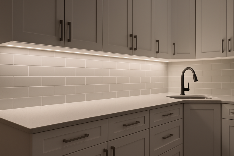
You’ve finished an expensive under-cabinet installation. The lights work perfectly, but the client points to the reflection on their new granite countertop. All they can see are distracting, cheap-looking dots of light.
Achieving a seamless installation requires three key elements: diffusing the light to eliminate hotspots using channels, planning all corners and connections to avoid dark spots, and meticulously hiding all power supplies and wiring for a clean, integrated finish.
As a manufacturer, I can provide the highest quality LED strip in the world, one with perfect color rendering and a long lifespan. But in the end, it’s the installer’s craftsmanship that determines the final look. The difference between a simple "peel-and-stick" job and a truly professional, architectural installation is all in the details. I’ve learned from my best clients in North America and Japan that they don’t just sell light; they sell a seamless effect. This guide will walk you through their exact techniques.
How Do You Eliminate Those Ugly LED "Dots" or Hotspots?
The cove lighting you installed is meant to provide a soft, ambient glow. Instead, it creates a scalloped, spotty pattern on the ceiling, making the whole room feel unfinished and cheap.
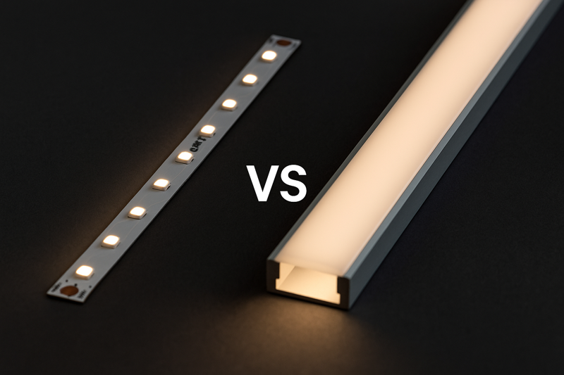
To eliminate hotspots, you must use an aluminum channel with a frosted or opal diffuser. The depth of the channel and the density of the LEDs on the strip are the key factors. A deeper channel and a higher LED density (LEDs/meter) will create a smoother, more uniform line of light.
This is the most common and visible mistake in LED strip installations. Seeing the individual points of light is a dead giveaway of an amateur job. For any application where the strip itself or its direct reflection is visible, using a channel and diffuser is not an optional upgrade; it is a mandatory component for a professional result. It’s the first thing a discerning client or designer will notice. They are paying for a beautiful lighting effect, not to see the hardware that creates it. When you use a channel, you are elevating the installation from a simple light source to a true architectural fixture.
The Physics of Diffusion
A seamless line of light is all about diffusion. You need to spread the light from each individual LED so that it overlaps with the light from its neighbors. Two main factors control this:
- Distance from LED to Diffuser1: The further the diffuser cover is from the LED chip, the more room the light has to spread out. This is why deeper channels produce a more seamless effect than very slim, shallow channels. A shallow channel might still show some slight spotting, while a deep channel will create a perfectly uniform line.
- Density of the LEDs2: The closer the LEDs are to each other, the easier it is for their light to overlap and blend. A strip with 60 LEDs per meter will be much spottier than a high-density strip with 120, 180, or even 240 LEDs per meter. For the most demanding applications, Chip-on-Board (COB) strips3, which have a continuous line of phosphor, offer a completely dot-free source even without a diffuser, but they still benefit from the protection and finished look of a channel.
Choosing the Right Channel and Diffuser Combination
Not all channels are created equal. You must match the channel to the specific needs of the project.
| Channel Type | LED Density | Resulting Effect | Best Use Case |
|---|---|---|---|
| Slim / Low-Profile | Low (60 LEDs/m) | Still Visible Spotting | Indirect lighting where the strip is completely hidden from view (e.g., inside a deep cove). |
| Slim / Low-Profile | High (120+ LEDs/m) | Mostly seamless, very faint spotting up close. | Under-cabinet, shelf lighting where a low profile is needed. |
| Deep / High-Profile | Any Density | Perfectly uniform, dot-free line of light. | Any application where the light fixture itself is visible and is a design element. |
| COB Strip (No Channel) | N/A | Dot-free source, but unprotected. | Only for dry, clean, indirect applications where a channel won’t fit. |
The diffuser material also matters. A clear cover offers protection but no diffusion. A frosted cover offers good diffusion with high light output. An opal or milky cover offers the best diffusion for the most seamless look but with a slight reduction in overall brightness. For most high-end jobs, the deep channel with an opal diffuser4 is the go-to professional choice.
What’s the Best Way to Handle Corners without Creating Dark Spots?
You’ve completed a beautiful, continuous run of light around a ceiling cove, but at every 90-degree corner, there’s an ugly, dark gap that breaks the seamless effect and draws the eye.
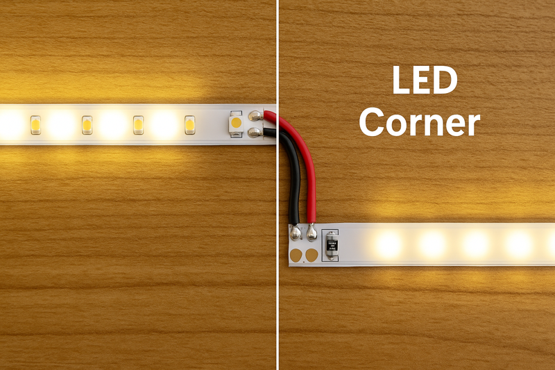
The most professional way to handle corners is to cut the strips and use short jumper wires soldered between the sections. This allows for a tight, clean corner with no dark spots and minimal stress on the strip. Solderless corner connectors are a faster but less reliable alternative.
Corners are a critical detail. A poorly made corner can ruin an otherwise perfect installation. The common amateur mistake is to try and bend the flexible strip itself at a sharp 90-degree angle. This seems logical, but it puts immense stress on the PCB, the solder joints, and the individual LEDs near the fold. Over time, this stress will cause that section of the strip to fail, leading to an expensive callback. Creating a clean, deliberate break and bridging it is the only way to ensure long-term reliability and a truly seamless look.
Comparing Corner Techniques
As an installer, you have three primary options for navigating a corner. The method you choose says a lot about the quality of your work.
- The Loop Method5 (Unprofessional): This involves creating a gentle, curved loop with the strip instead of a sharp bend. While it avoids stressing the strip, it’s virtually impossible to hide the loop, and it creates a bright spot on one side and a shadow on the other. It looks messy and is not a professional solution.
- Solderless "L-Shape" Connectors6: These are plastic clip-on connectors shaped like an ‘L’. You cut your strips and slide the ends into either side of the connector.
- Pros: They are very fast to install and require no special tools like a soldering iron7.
- Cons: This is their critical weakness: they are notoriously unreliable. The metal contacts inside the clip only make a pressure connection with the copper pads on the strip. Over time, vibrations, temperature changes, or humidity can cause this connection to loosen or oxidize, leading to flickering or complete failure of the strip beyond that point. I have received countless support calls from installers that were ultimately traced back to a failed solderless connector.
- Soldering Jumper Wires8 (The Professional Standard): This is the superior method used by all high-end installers.
- Process: You cut the two strips precisely at the corner. Then you take a short piece of appropriate gauge wire (e.g., 2-3 inches of 20AWG wire) and solder it from the copper pads of the first strip to the corresponding pads on the second strip.
- Pros: A soldered joint is a permanent, metallurgical bond. It is the most electrically and mechanically reliable connection possible. It will not loosen or fail over time. It also allows for perfect, tight corners with zero light gap.
- Cons: It requires a soldering iron and a basic level of skill. However, learning to make a clean solder joint is a fundamental skill that every professional lighting installer should possess. It’s what separates the experts from the amateurs.
How Do You Join Two Strips to Create One Long, Continuous Run?
Your project requires 30 feet of lighting, but your LED strips come in 16.4-foot (5-meter) reels. You connect them end-to-end, but the second strip is noticeably dimmer than the first, ruining the seamless look.
To create long, seamless runs, you must use parallel wiring to overcome voltage drop. Run a separate, heavier-gauge power wire from the power supply alongside the strips and power each new 5-meter section directly from this main power line. Never connect strips in series beyond their maximum recommended length.
This is one of the most common technical mistakes I see. An LED strip is essentially a long, thin circuit board. The thin copper traces on the strip have electrical resistance. When you try to push power through a very long run of these traces, the resistance adds up, causing the voltage to "drop" along the length. A 24V strip might receive the full 24 volts at the beginning, but by the time the power travels 10 meters down the strip, the voltage might have dropped to 21V. This lower voltage causes the LEDs at the far end to be significantly dimmer and can even cause a shift in color temperature. This completely destroys the seamless effect.
The Parallel Wiring Solution
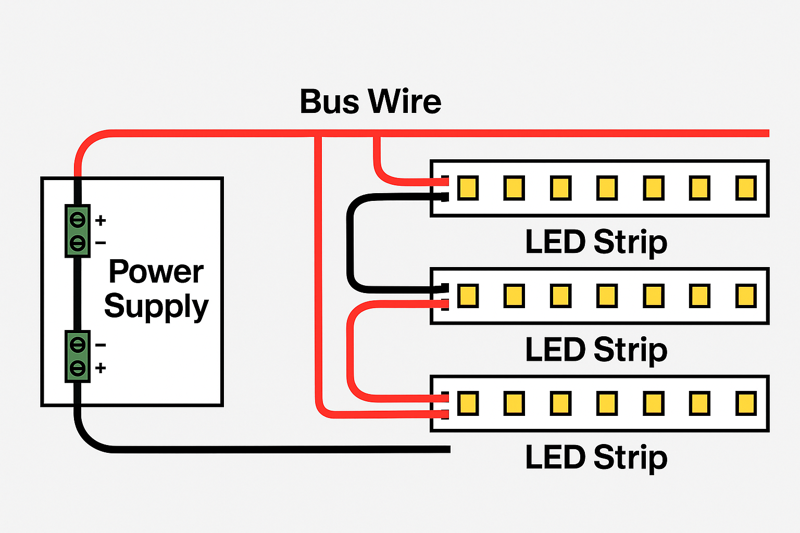
The professional solution is to not use the strip itself to carry power over long distances. Instead, you run a separate, appropriately sized "bus" or "feeder" wire in parallel with your installation.
Step-by-Step Implementation:
- Calculate Total Load: First, determine the total wattage and amperage of your entire run (e.g., 30 feet of our 4.4W/ft strip is 132W total. At 24V, this is 132W / 24V = 5.5 Amps).
- Choose Your Power Wire: Based on the total amperage and the distance from the power supply, select the correct American Wire Gauge (AWG)9 for your feeder wire10. For a 5.5 Amp load over 30 feet, a 16 AWG or 14 AWG wire would be a safe and professional choice.
- Run the Feeder Wire: Place your power supply at the beginning or middle of the run. Run your chosen two-conductor feeder wire from the power supply’s output terminals along the entire length of the planned installation, hiding it inside the channel or cove.
- Power Each Section:
- Install the first 16.4-foot (5m) strip. Solder its power leads directly to the feeder wire.
- Butt the second strip right up against the end of the first one for a physically seamless look.
- Solder the power leads of this second strip to the same feeder wire.
- Repeat for every new section.
This method ensures that every single section of the LED strip is receiving the same, full voltage directly from the power source, resulting in perfectly uniform brightness and color from the beginning of the run to the very end.
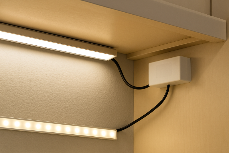
Where Should You Hide the Power Supply and All the Wiring?
The light from the strip is perfectly diffused and continuous, but there’s a bulky black power supply sitting on the floor and visible wires running up the wall, completely ruining the clean, integrated look.
The power supply and wiring must be planned for and hidden before the installation. Ideal locations include inside cabinets, above drop ceilings, in nearby closets or pantries, or within a ventilated custom enclosure. The goal is to make the lighting feel like it appears from nowhere.
This is the final step that ties the entire seamless installation together. Meticulous wire management and power supply placement are just as important as the light itself. A visible "wall-wart" style power adapter or tangled wires instantly cheapens the entire project. For my clients who are contractors and designers, planning for this from the start is a key part of their process. They coordinate with electricians and cabinet makers to ensure that low-voltage wiring can be run inside walls and that dedicated, ventilated spaces are created for the drivers. This level of forethought is what defines a high-end, professional installation.
Common Hiding Strategies
The best location depends entirely on the project’s layout, but here are the most common and effective solutions used by professionals:
- Inside Cabinetry: This is the most popular choice for kitchen under-cabinet lighting. The power supply can be mounted on its side inside the upper cabinet (often above the refrigerator) or in the lower cabinet, with a small hole drilled to pass the low-voltage wire to the strip.
- In a Closet or Pantry: If the installation is near a closet, pantry, or utility room, this is a perfect place to house a larger power supply. You can run the low-voltage wire through the wall for a completely invisible transition.
- Above a Drop Ceiling: In commercial spaces or basements with drop ceilings, the space above the tiles is an ideal, accessible, and well-ventilated location for multiple power supplies.
- Basements or Crawl Spaces: For installations on the main floor, sometimes the easiest path is to drill down and place the power supply in the unfinished basement or crawl space below, running the wire up inside the wall cavity.
- In-Wall Power Supply Boxes: Several companies now make specialized recessed enclosures that allow certain types of power supplies to be safely installed flush within a wall cavity, hidden behind a blank faceplate.
Always consider ventilation. Power supplies generate some heat and need airflow to operate safely and reliably. Never bury them in insulation or cram them into a tiny, unventilated box. Planning for placement and wiring paths from the beginning turns a simple lighting element into a truly integrated and seamless architectural feature.
Conclusion
Creating a seamless installation is about mastering the details. It’s about moving beyond simply making lights turn on and focusing on how the light is delivered—diffused, continuous, and with no visible hardware.
-
Understanding this concept is crucial for achieving optimal light diffusion in your projects. ↩
-
Exploring this topic will help you choose the right LED density for seamless lighting effects. ↩
-
Learn about COB strips to enhance your lighting design with a dot-free source. ↩
-
Discover why this combination is favored by professionals for achieving seamless lighting. ↩
-
Exploring the drawbacks of the Loop Method can help you avoid common mistakes and improve your installation skills. ↩
-
Understanding the pros and cons of these connectors can help you make informed decisions for your projects. ↩
-
Finding the right soldering iron can significantly impact your soldering quality and overall project success. ↩
-
Learning the correct soldering techniques ensures reliable connections and enhances the quality of your installations. ↩
-
Understanding AWG is crucial for selecting the right wire size for your projects, ensuring safety and efficiency. ↩
-
Exploring feeder wire applications can enhance your knowledge of electrical systems and improve your installation techniques. ↩
Interested in Our LED Solutions?
Get professional consultation and customized LED lighting solutions for your projects. Contact our expert team today.
Related Articles

How Do You Build Profitable Custom Vehicle and RV Interior LED Rope Lights?
You lose RV installation contracts because your interior lights fail on rough roads. Standard strips show bright dots on glossy…

How to Perfect Bookshelf and Display Cabinet LED Rope Lighting?
You lose retail clients when bookshelves look incredibly dark. Ugly shadows hide expensive products inside display cabinets daily. You need…

How to Master Mirror and Vanity LED Rope Light Installation?
Your clients complain about ugly shadows in their bathroom mirrors. Bad lighting ruins expensive vanity designs. You lose future contracts…
