
How Do You Wire LED Strip Lights for a Professional Installation?
Your project is complete, the design is perfect, but a week later the client calls. The lights are flickering in one section. A simple wiring mistake has now turned into a costly service call, damaging your schedule and your reputation.
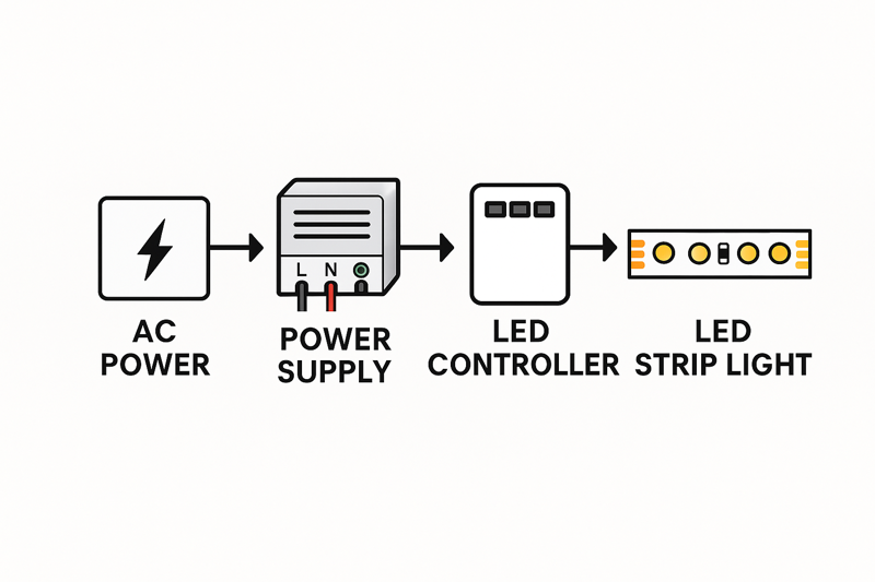
Professional wiring involves creating secure, low-voltage connections from a correctly sized power supply to the LED strip, ensuring correct polarity. For controls, the dimmer is wired between the supply and the strip. For multiple strips, parallel wiring is essential to prevent voltage drop.
As a manufacturer, I’ve seen everything. I can tell the quality of an installation not just from the light output, but from the wiring behind the scenes. A messy, poorly planned wiring job is a signal of future problems. For my clients, who are professionals building a business, every connection is a reflection of their brand. This guide isn’t about just making the lights turn on; it’s about building a robust system that you can install with confidence and then walk away from, knowing it will perform flawlessly for years.
What Essential Components and Tools Do You Need Before You Start?
You’re on-site, the clock is ticking, and you realize you have the wrong gauge of wire for the extension. The project halts, you have to run to a supplier, and your entire schedule for the day is thrown off.
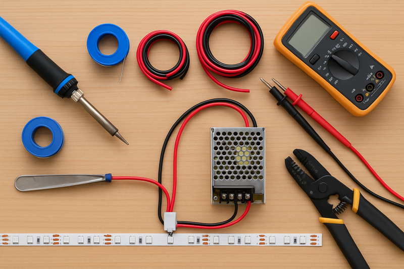
Before starting, gather your specific LED strip, the correctly calculated power supply, proper gauge DC wire, soldering equipment, and basic hand tools like wire strippers and a multimeter. Having every component ready eliminates on-site delays and ensures a smooth installation process.
I’ve learned this lesson from watching hundreds of my clients, from lighting designers in Japan to contractors in the United States. The most successful ones are meticulous planners. They treat the preparation phase with the same importance as the final installation. Creating a simple kit with all the necessary tools and components for a standard job saves countless hours and prevents the costly mistakes that come from improvisation.
Choosing the Right Wire Gauge (AWG)
The wire connecting your power supply to your strip is not just a simple conductor; it’s a critical component of the system. Using a wire that is too thin (a higher American Wire Gauge1 or AWG number) for the current it needs to carry is a massive mistake. The thin wire has higher resistance, which causes two huge problems: it heats up, creating a potential safety hazard, and it causes its own voltage drop before the power even reaches the strip. This can dim your lights and reduce the efficiency of the entire system. You must select the wire gauge based on the total amperage of your LED strip run and the length of the wire itself.
For a professional 24V system, which we recommend, the current is lower, allowing for more flexible wire choices. However, the principle remains the same. A longer distance requires a thicker wire (lower AWG) to carry the same current without significant loss.
| Total Current (Amps) | Max Wire Length (Feet) | Recommended AWG (Copper Wire) |
|---|---|---|
| 0-5 Amps | 0 – 20 feet | 18 AWG |
| 0-5 Amps | 20 – 40 feet | 16 AWG |
| 5-10 Amps | 0 – 20 feet | 14 AWG |
| 5-10 Amps | 20 – 40 feet | 12 AWG |
Essential Tools for a Professional Kit
Beyond the obvious, a professional’s toolkit contains items that separate a good installation from a great one.
- A Quality Multimeter2: This is non-negotiable. Use it to confirm the output voltage of your power supply before connecting the strip. Use it to check for correct polarity (+/-) on your wires. Use it to troubleshoot a failed section by checking for continuity. It’s an inexpensive tool that can save you from a very expensive mistake, like connecting a 12V strip to a 24V supply.
- Soldering Iron and Supplies3: As I’ve said before, soldering is the only truly permanent connection method. A good 60W temperature-adjustable soldering iron, lead-free solder, and flux are essential.
- Heat Gun and Heat Shrink Tubing4: For protecting your soldered connections, nothing beats adhesive-lined heat shrink tubing. When heated, it shrinks to form a tight, rigid, and waterproof seal around the joint, providing both electrical insulation and mechanical strain relief. This is the mark of a truly professional finish.
How Do You Connect a Single LED Strip to a Power Supply?
You’ve unboxed the components. The power supply has multiple terminals and the LED strip has two small wires. A wrong connection could instantly destroy the entire reel of expensive, high-CRI strip lights you just purchased.
First, ensure the power is off. Connect the positive (+) wire from the LED strip to the positive (+) DC output terminal on the power supply. Connect the negative (-) wire to the negative (-) terminal. Double-check the polarity before restoring power.

This is the most fundamental connection in any LED system. While it seems incredibly simple, this is where costly, irreversible mistakes are made. I once had a new client, a contractor, call me in a panic because he had "fried" three reels of our strips in a row. The cause was a simple polarity reversal. He was rushing and wasn’t double-checking his connections. Taking an extra 10 seconds to verify that positive connects to positive and negative to negative is the cheapest insurance you can have on a project.
Connecting to a Power Supply with Screw Terminals
Most professional-grade power supplies, like the ones we pair with our strips, don’t have a simple barrel plug. They have a more robust screw terminal block5 for a secure connection.
- Safety First: Disconnect the power supply from the main AC power6. Never work on live electrical components.
- Prepare the Wires: Strip about a quarter-inch (5-6mm) of insulation from the positive and negative wires coming from your LED strip. If the wire is stranded, give it a gentle twist to keep the strands together. For the absolute best connection, tinning the stripped ends7 with a little solder makes them more solid and easier to clamp down.
- Identify Terminals: Look at the DC output side of your power supply. It will be clearly marked, typically with "V+", "+V", or just "+" for positive, and "V-", "-V", or just "-" for negative. There will also be AC input terminals (L, N, Ground), which should be handled by a qualified electrician.
- Make the Connection: Loosen the corresponding screws on the terminal block. Insert the tinned positive wire into the V+ terminal and the negative wire into the V- terminal. Ensure no stray wire strands are touching adjacent terminals.
- Secure the Connection: Tighten the screws firmly, but do not over-tighten, which can damage the wire or the terminal. Give the wires a gentle tug to ensure they are securely clamped. A loose connection here can cause arcing, flickering, and is a potential fire hazard.
Testing the Connection Safely
Before you mount the strip in its final location, it’s wise to perform a quick test. Place the strip on a non-conductive surface. Triple-check your polarity8. Now, stand back and restore AC power to the power supply. The strip should light up to its full, uniform brightness. If it doesn’t, or if you see any smoke or smell anything burning, disconnect the power immediately and re-check your work. This simple test, done on a workbench or the floor, can save you the immense frustration of having to troubleshoot an installation that is already mounted in a hard-to-reach ceiling cove.
How Should You Wire a Dimmer or Controller?
Your client wants to be able to control the brightness, or for an RGB strip, the color. You have a strip, a power supply, and a controller. Where does the controller go in the circuit?
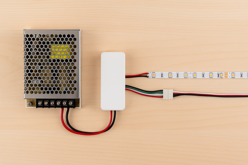
The controller or dimmer is always wired on the low-voltage side of the circuit. It goes between the power supply and the LED strip. The power supply’s DC output connects to the controller’s input, and the controller’s output connects to the strip.
 LED strip9 with a PWM (Pulse Width Modulation) dimmer10, which is the most common type.
-
Power Supply to Dimmer Input:
- Connect the V+ output of the power supply to the "VIN+" or "Input+" terminal on the dimmer.
- Connect the V- output of the power supply to the "VIN-" or "Input-" terminal on the dimmer.
- Use the same gauge wire you would use to connect directly to the strip.
-
Dimmer Output to LED Strip:
- Connect the "VOUT+" or "Output+" terminal on the dimmer to the positive (+) wire of your LED strip.
- Connect the "VOUT-" or "Output-" terminal on the dimmer to the negative (-) wire of your LED strip.
Essentially, you are inserting the dimmer directly into the wiring path. The power supply provides a constant 24V to the dimmer. The dimmer then "chops" that power using PWM to control the brightness and sends the modulated signal to the LED strip.
Wiring an RGB or RGBW Controller11
The concept is exactly the same for a multi-channel controller, but you have more output wires to manage.
- Input Connection: The input from the power supply is the same: V+ to input V+, V- to input V-.
- Output Connections: The output side will have terminals for each color channel plus a common positive.
- The "V+" or "Common" output terminal connects to the positive wire on your RGB/W strip (this is usually the black or white wire).
- The "R" or "Red" output terminal connects to the red wire on the strip.
- The "G" or "Green" output terminal connects to the green wire on the strip.
- The "B" or "Blue" output terminal connects to the blue wire on the strip.
- (If using an RGBW strip) The "W" or "White" output terminal connects to the white wire on the strip.
It is absolutely crucial to match these outputs correctly. Mismatching the R, G, and B wires will cause your color controls to work incorrectly (e.g., pressing red on the remote makes the lights turn green). Taking a moment to organize and label your wires before making the connections can save a lot of frustration.
What’s the Correct Way to Wire Multiple Strips to One Power Supply?
The project requires 15 meters of light, but your reels are 5 meters long. The common instinct is to simply plug the end of the first strip into the beginning of the second, and so on. This is a guaranteed failure.
You must use a parallel wiring configuration. Run separate wires from the power supply’s output terminals to the start of each individual strip, or use a thicker gauge "bus" wire that runs alongside and taps into each strip. Never connect strips end-to-end beyond the recommended maximum run length.
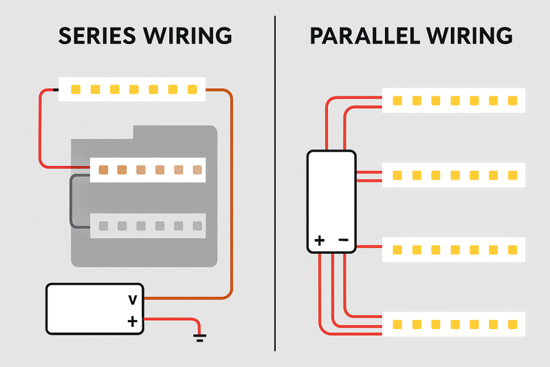
This is probably the most important technical concept for a professional installer to master. I have seen more projects compromised by improper series connections than by almost any other issue. Connecting strips in series over long distances is the primary cause of voltage drop, which leads to dimming, color shifting, and overworked, overheating strips at the beginning of the run. A parallel connection ensures that every single strip receives the full, correct voltage directly from the source.
Parallel Wiring Methods
Let’s say you have a large ceiling cove that requires three 5-meter strips, all running from a single, high-wattage power supply. Here are two professional ways to wire this:
-
Direct Connection (Home Run):
- This is the simplest and often the best method if the power supply is centrally located.
- Run one dedicated pair of wires from the power supply’s V+/V- terminals directly to the first 5-meter strip.
- Run a second, separate pair of wires from the same V+/V- terminals to the beginning of the second strip.
- Run a third, separate pair of wires from the same V+/V- terminals to the beginning of the third strip.
- All three pairs of wires connect together at the power supply’s output. This ensures each strip gets its own clean supply of power.
-
Using a "Bus" or "Spine" Wire:
- This method is better when the power supply is at one end of a very long installation.
- Run one pair of heavy-gauge wires (e.g., 14 AWG) from the power supply along the entire 15-meter length of the installation. This is your "power bus."
- At the beginning of the first strip, tap into this bus wire to power the strip.
- At the 5-meter mark (the start of the second strip), tap into the bus wire again to power the second strip.
- At the 10-meter mark (the start of the third strip), tap into the bus wire a final time.
- This approach uses the heavy gauge wire to carry the power over the long distance with minimal voltage drop, and the strips themselves only have to carry power over their own 5-meter length.
| Method | Best Use Case | Pros | Cons |
|---|---|---|---|
| Direct (Home Run) | When power supply can be centrally located. | Easiest to understand; most balanced power delivery. | Can use a lot of wire if strips are far from the supply. |
| Bus / Spine Wire | Long, continuous runs where the power supply is at one end. | More wire-efficient for long, straight installations. | Requires making secure taps into the main wire, which needs care. |
Choosing the right method depends on the physical layout of your project. The key principle is the same: avoid forcing the electrical current to travel through 15 meters of thin copper PCB trace on the strip itself.
Conclusion
Correct wiring is not a shortcut you can afford to take. By using these professional, step-by-step techniques, you ensure that your lighting projects are safe, reliable, and perform exactly as you designed them to.
-
Understanding AWG is crucial for selecting the right wire gauge, ensuring safety and efficiency in your electrical projects. ↩
-
A quality multimeter is essential for accurate voltage readings and troubleshooting, making it a must-have for any electrical work. ↩
-
Choosing the right soldering iron and supplies ensures durable connections, preventing future electrical issues in your projects. ↩
-
Heat shrink tubing provides excellent protection for electrical connections, ensuring longevity and safety in your installations. ↩
-
Understanding screw terminal blocks is essential for secure electrical connections, ensuring safety and reliability in your projects. ↩
-
Learning about AC power is crucial for anyone working with electrical systems, enhancing your knowledge and safety. ↩
-
Tinning wires improves connection quality, making your electrical projects safer and more efficient. ↩
-
Understanding polarity is vital for preventing electrical issues and ensuring your devices function correctly. ↩
-
Explore the various types of LED strips to find the best fit for your project. This link offers comprehensive information. ↩
-
Understanding PWM dimmers is essential for effective LED control. Explore this link to learn about their functionality and benefits. ↩
-
Discover the intricacies of RGBW controllers to enhance your LED lighting experience. This resource provides valuable insights. ↩
Interested in Our LED Solutions?
Get professional consultation and customized LED lighting solutions for your projects. Contact our expert team today.
Related Articles

How Do You Build Profitable Custom Vehicle and RV Interior LED Rope Lights?
You lose RV installation contracts because your interior lights fail on rough roads. Standard strips show bright dots on glossy…

How to Perfect Bookshelf and Display Cabinet LED Rope Lighting?
You lose retail clients when bookshelves look incredibly dark. Ugly shadows hide expensive products inside display cabinets daily. You need…

How to Master Mirror and Vanity LED Rope Light Installation?
Your clients complain about ugly shadows in their bathroom mirrors. Bad lighting ruins expensive vanity designs. You lose future contracts…
