
Why Isn’t Your LED Strip Working? A Complete Diagnostic Checklist
The installation is complete, the wires are hidden, and you flip the switch for the grand reveal… but nothing happens. An entire section is dark. The client is waiting, and every second of troubleshooting on-site is costing you money and reputation.
A non-working LED strip is rarely a defective product. The issue is almost always a failure in the power delivery system. The most common causes are a dead power supply, a broken electrical connection, or incorrect polarity in the wiring between the components.
As a manufacturer, I handle technical support for clients like Tom all the time. The first email I get is often, "Your strips are dead on arrival." I understand the frustration, but my years of experience have shown that the LED strip itself is the most robust part of the entire system. It’s just a series of simple diodes on a flexible circuit board. The real points of failure are the active electronic components (the power supply) and the physical connection points. Before you start ripping strips off the wall, you need a systematic, professional diagnostic checklist. We will follow the path of electricity, from the wall outlet to the strip itself, to find the true source of the problem in minutes, not hours.
Is Your Power Supply the Real Problem?
You’ve plugged everything in, but the strip is completely dead. There’s no light, no flicker, nothing. You grab another new strip from the box, connect it, and it’s also dead. Is it a bad batch of strips?
Almost certainly not. A completely dead strip usually indicates a total lack of power. The first and most likely culprit is a faulty or improperly connected power supply (driver). You must verify it is receiving AC input and providing DC output.
This is square one. The power supply is the heart of your lighting system; it converts the high-voltage AC from the wall into the low-voltage DC that the LED strips need. If the heart isn’t pumping, the system is dead. I’ve seen installers waste hours troubleshooting wiring and controllers when the power supply was never even turned on or had failed entirely. A surprising number of drivers are damaged by being wired incorrectly on the high-voltage AC side, which instantly destroys the internal components. Making assumptions here is the costliest mistake you can make. The only way to know for sure is to get out your multimeter. It’s the most essential tool for any lighting professional. Without it, you are just guessing, and guessing costs money.
A Deeper Dive into Power Supply Diagnostics
For a professional like Tom, who manages multiple projects, being able to quickly and definitively test a power supply is a core skill. It separates the pros from the amateurs. Let’s break down the step-by-step process I use myself.
-
Step 1: Verify AC Input1 (The Power Into the Driver)
Your power supply can’t create power, it only converts it. First, confirm it’s getting power from the building.- Safety First: Ensure the power is on at the breaker. If it’s a plug-in style power supply, test the wall outlet with a lamp or another device to confirm it’s live.
- Use Your Multimeter2: Set your multimeter to AC Voltage mode (V~ or VAC).
- Test the Input: Carefully touch the probes to the AC input terminals (usually marked L for Line and N for Neutral) on the power supply.
- Expected Reading3: You should see a reading that corresponds to your local mains voltage (e.g., ~120V in North America, ~230V in Europe).
- No Reading? If you get 0V here, the problem is in the building’s wiring leading to your power supply. The driver itself is not getting power.
-
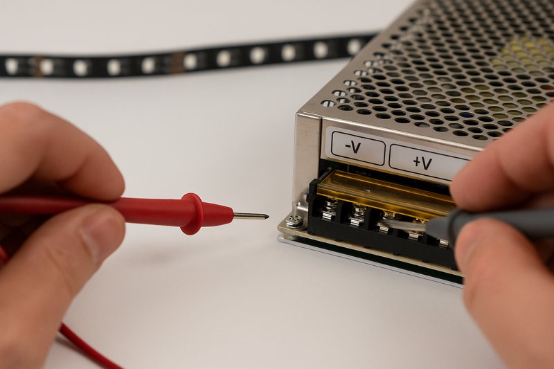
Step 2: Verify DC Output4 (The Power From the Driver)
If the AC input is good, the next step is to see if the driver is doing its job and converting that power.- Set Your Multimeter: Switch your multimeter to DC Voltage mode (V⎓, V—, or VDC).
- Test the Output: Touch the probes to the DC output terminals (usually marked + and – or V+ and V-).
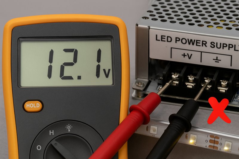
- Expected Reading: You should see a reading that matches the power supply’s rating (e.g., ~12V or ~24V). A small variance is okay (e.g., 12.1V for a 12V supply).
- No Reading? If you have confirmed AC input but you get 0V on the DC output, the power supply is faulty and needs to be replaced. There is no other conclusion. This single test can save you from needlessly uninstalling your entire lighting run.
| Test Point | Multimeter Setting | Expected Reading (USA) | Diagnosis of 0V Reading |
|---|---|---|---|
| AC Input | V~ (AC Voltage) | ~120V | Problem is with the building’s wiring or the outlet. |
| DC Output | V⎓ (DC Voltage) | ~12V or ~24V | Power supply is confirmed faulty and must be replaced. |
Are Your Connections Securely Delivering Power?
Your power supply is working perfectly—you’ve tested it and it’s putting out a stable 12V. But when you connect the strip, it remains dark. What is happening between the power supply and the strip?
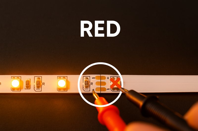
A working power supply means nothing if that power doesn’t reach the strip. A loose wire, a bad solder joint, an incorrect solderless connector, or reversed polarity will create an open circuit, stopping the flow of electricity.
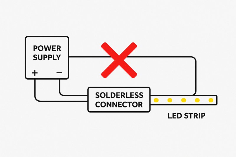
This is the second most common failure point. Electricity needs a complete, unbroken path to flow. Any weak link in that chain will kill the entire system. I often see this with solderless, or "clip-on," connectors. They are convenient, but they are also a frequent source of problems. The tiny metal teeth inside them must perfectly align with and pierce the copper pads on the strip. If they are misaligned, oxidized, or clogged with the strip’s waterproof silicone coating, they won’t make a solid connection. Another simple but common mistake is reversing the polarity. Connecting the positive wire to the negative terminal (and vice-versa) won’t damage the strip, but it will prevent it from lighting up.
A Deeper Dive into Connection Integrity
For a project manager like Tom, callbacks to fix a loose wire are pure lost profit. Ensuring every connection is perfect during the initial installation is crucial. This is a matter of process and discipline.
-
Testing for Continuity5
Continuity is an electrical term for a complete, unbroken path. A multimeter’s continuity test function6 is your best friend here.- Disconnect Power: Unplug the power supply completely.
- Set Your Multimeter: Turn the dial to the continuity setting (it often looks like a sound wave symbol: ))). When you touch the probes together, the meter should beep.
- Test the Positive Side: Place one probe on the V+ screw terminal of the power supply. Place the other probe on the copper pad marked "+" at the start of your LED strip. The meter should beep, confirming an unbroken positive path. No beep means there is a break somewhere in your positive wire or connector.
- Test the Negative Side: Repeat the process for the negative path, from the V- terminal to the "-" copper pad. It should also beep.
- No Beep? If either test fails, you must meticulously inspect every inch of the wire and every connection point. Is the wire securely in the terminal? Is the solderless connector properly seated? Is your solder joint "cold" and cracked7?
-
Soldering vs. Solderless Connectors8: A Professional’s Choice
While we supply solderless connectors for convenience, I always advise my top-tier clients to invest in soldering for permanent installations.
| Feature | Solderless "Clip-on" Connectors | Soldered Connections |
|---|---|---|
| Reliability | Moderate. Prone to failure from vibration/flex. | Extremely high. Creates a single, fused connection. |
| Installation Speed | Very Fast. Requires no special tools. | Slower. Requires a soldering iron and skill. |
| Best Use Case | Temporary setups, DIY projects, quick mock-ups. | Professional architectural and permanent installs. |
| Common Failure Mode | Poor contact, misalignment, corrosion. | "Cold" joints from improper technique. |
Tom, I know your installers are on a tight schedule, but training them to solder properly is an investment that will pay for itself by eliminating callbacks for faulty connections.
What if Only the First Part of the Strip Lights Up?
You’ve connected a long 15-foot run of LED strip. The first few inches or first foot lights up perfectly, but the rest of the strip is completely dark. Is the strip broken after that point?
This classic symptom indicates a break in the circuit on the strip itself. Since LEDs are wired in series within small segments, a single failed component or a crack in the flexible PCB will prevent power from reaching the rest of the strip.
This is one of the few times the problem is actually located on the strip itself, but it’s rarely a manufacturing defect. An LED strip is a flexible printed circuit board (PCB). If you bend it too sharply, especially at a 90-degree angle, you can crack the copper traces that carry the electricity. The LEDs themselves are wired in series in small groups (usually 3 or 6 LEDs). If you break the circuit at any point, all the segments "downstream" from that break will lose power and go dark. This issue almost always happens at a point where the strip was bent or physically stressed during installation.
A Deeper Dive into On-Strip Circuit Failures
Understanding how a strip is constructed helps you diagnose and fix this problem efficiently. You don’t need to replace the entire strip; you just need to bypass the break.
-
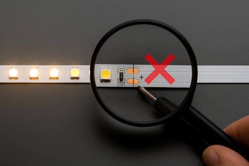
Understanding the "Series Groups9"
Look closely at your LED strip. You’ll see designated "cut lines10," usually marked with a scissor icon, every few inches. The section between two cut lines is an independent, self-contained series circuit.- How it Works: Within that small segment (e.g., 3 LEDs and a resistor), the current flows from the positive trace, through each LED in order, through the resistor, and to the negative trace. The main power rails (+ and -) run the entire length of the strip in parallel to supply power to each of these small, independent segments.
- The Failure Point: If you step on the strip, bend it too sharply, or damage a single LED or resistor in one of these segments, you break that specific series circuit. But more importantly, if you crack the main parallel power rail running alongside that segment, you cut off power to every other segment further down the line. This is why the first part lights up and the rest is dead.
-
The Diagnostic & Repair Process
- Identify the Breakpoint: The point of failure is almost always on or right next to the last working LED segment.
- Inspect Closely: Look for any signs of physical damage: a crease, a crack, a discolored component.
- Confirm with a Multimeter: Use your multimeter’s continuity test11. Check the positive and negative power rails across the suspected break. For instance, put one probe on the "+" pad just before the last lit segment and the other probe on the "+" pad just after it. If it doesn’t beep, you’ve confirmed the break in the power rail.
- The Fix: You don’t need to replace the whole strip. You can simply cut out the single damaged segment at the designated cut lines. Then, use a solderless connector12 or, preferably, solder small jumper wires to bridge the gap and reconnect the two now-separate pieces of the strip. This bypasses the break and restores power to the rest of the run.
Why Are Some Colors Missing or Incorrect?
Your RGB or RGBW strip lights up, but you have a problem. When you select red, it looks yellow. When you select blue, it looks purple. Or maybe the red channel doesn’t work at all, no matter what.
Incorrect or missing colors on a multi-channel strip are almost never a problem with the LEDs. This issue is caused by a poor connection on one of the specific color channels (R, G, or B) or a misconfiguration in the controller.
This is a data and connection problem, not a power problem. An RGB strip has four separate connections: one for positive power (+) and one for each color channel (Red, Green, Blue). If the main power connections are good, the strip will light up. But if the connection for the Red channel is loose or broken, no power will ever get to the red LEDs. If you try to select red, nothing will happen. If you try to select purple (which is a mix of red and blue), only the blue LEDs will light up, so the strip will appear blue. If the connection is just weak or intermittent, you’ll get strange color mixing issues, flickering on that specific color, or colors that look "wrong."
A Deeper Dive into Multi-Channel Connections
For clients like Tom working in architectural lighting, color accuracy is paramount. An "off-white" or a "yellowish-red" is unacceptable. Mastering these multi-channel connections is crucial.
-
The Connection is the Culprit (99% of the time)
Your diagnostic process should focus entirely on the path of the signal from the controller to the strip.- Check the Controller Terminals: Ensure the wires are securely fastened in the screw-down terminals of your controller. Are the R, G, B, and W wires in the correct corresponding terminals? It’s very easy to mix these up.
- Inspect the Connectors: This is where solderless connectors create the most problems. An RGB strip has 4 tiny copper pads. A 4-pin clip-on connector must align perfectly with all of them. It is very common for one of the pins to be slightly misaligned, causing that single color to fail.
- Wiggle Test: With the power on and a single color selected (e.g., pure red), gently wiggle the connector and the wire between the controller and the strip. If the red color flickers or suddenly appears, you have found your loose connection.
- Again, Soldering is King: For multi-channel strips, the reliability of a soldered connection is even more critical than for single-color strips. It is the only way to guarantee that all four (or five, for RGBW) channels have a perfect, durable electrical bond.
-
Controller Configuration
While less common, some advanced DMX or digital controllers need to be configured.- Channel Order: Is your controller programmed to output signals in the order of RGB, but your strip is wired with a GRB channel order? This will cause the colors to be swapped (e.g., selecting red on your remote makes the strip green). Check the controller’s manual to ensure the channel mapping matches the physical wiring of your strip.
| Symptom | Most Likely Cause | Professional Solution |
|---|---|---|
| One Color Completely Missing | Broken wire or pin connection for that color channel. | Re-seat connector or solder the wire for that channel. Check continuity. |
| Colors are Swapped | Wires are in the wrong terminals on the controller. | Verify R, G, B, W wiring order matches controller outputs. |
| Strange Color Mixing | A weak/intermittent connection on one color channel. | Perform a "wiggle test" to locate the loose point; solder to fix. |
| All Colors Work Near Controller | Voltage drop on the color channels over a long run. | Inject additional power to the strip further down the line. |
Conclusion
Stop blaming the product. A dead LED strip is a symptom of a dead system. Master this diagnostic checklist—test the power, verify the connections, and inspect the strip—to find the root cause quickly, fix it professionally, and protect your profit.
-
Understanding how to verify AC input is crucial for troubleshooting power supply issues effectively. ↩
-
Learning to use a multimeter correctly can significantly enhance your diagnostic skills and efficiency. ↩
-
Familiarizing yourself with expected readings helps in quickly identifying faults in power supplies. ↩
-
Knowing how to verify DC output ensures that your power supply is functioning correctly, preventing unnecessary replacements. ↩
-
Understanding continuity testing is essential for ensuring reliable electrical connections, reducing future issues. ↩
-
Learning how to effectively use a multimeter can enhance your troubleshooting skills and ensure better installations. ↩
-
Understanding the causes of cold solder joints can help you avoid common pitfalls in electrical work. ↩
-
Exploring the pros and cons of each method can help you make informed decisions for your projects. ↩
-
Understanding Series Groups is crucial for diagnosing LED strip failures effectively. ↩
-
Exploring cut lines helps you understand how to repair LED strips without replacing them. ↩
-
Learning to use a multimeter’s continuity test can save you time and money in repairs. ↩
-
Discovering solderless connectors can simplify your LED strip repair process significantly. ↩
Interested in Our LED Solutions?
Get professional consultation and customized LED lighting solutions for your projects. Contact our expert team today.
Related Articles

How Do You Build Profitable Custom Vehicle and RV Interior LED Rope Lights?
You lose RV installation contracts because your interior lights fail on rough roads. Standard strips show bright dots on glossy…

How to Perfect Bookshelf and Display Cabinet LED Rope Lighting?
You lose retail clients when bookshelves look incredibly dark. Ugly shadows hide expensive products inside display cabinets daily. You need…

How to Master Mirror and Vanity LED Rope Light Installation?
Your clients complain about ugly shadows in their bathroom mirrors. Bad lighting ruins expensive vanity designs. You lose future contracts…
