How to Calculate Power Supply Requirements for LED Strip Installations
Why Power Supply Sizing Is the Most Preventable Source of LED Strip Failure
In post-installation failure analysis of LED strip systems, power supply problems—undersizing, incorrect voltage, or improper derating—account for an estimated 35–40% of field failures according to DOE SSL program data.1 Almost all are preventable with a simple calculation performed before procurement. This guide provides the complete sizing methodology: from raw load calculation through derating, voltage drop management, inrush current, and power supply type selection.
The mathematics involved is straightforward. The engineering discipline is in applying it consistently—including for cases where the temptation is to round down, reuse an existing driver, or assume a margin that was not actually calculated.
Step 1: Calculate Total Wattage
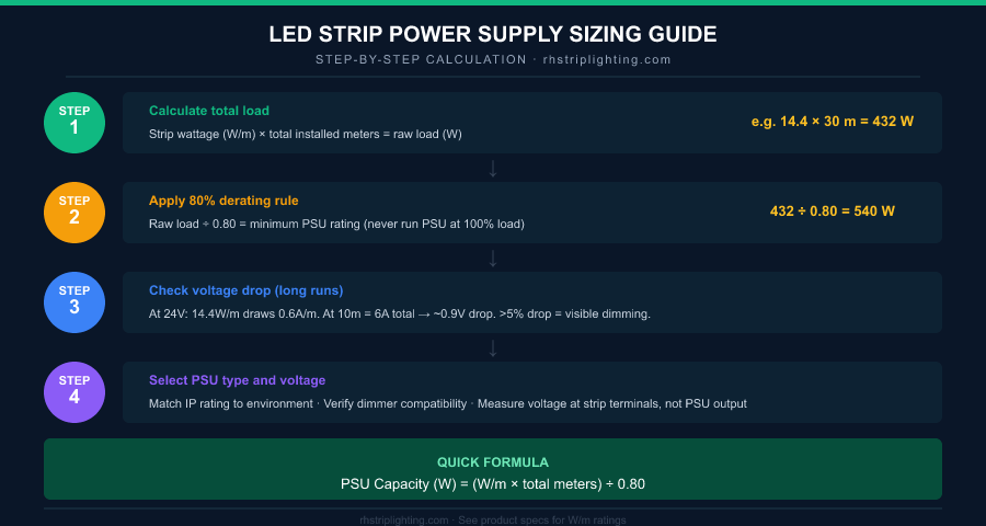
Every LED strip product specification includes a rated wattage per linear metre (W/m). This is the steady-state power draw at full brightness, measured at the rated voltage. Multiply this by total installed length in metres.
If your installation includes multiple strip types—for example, a mix of 14.4 W/m single-color strips and 7.2 W/m tunable white strips—calculate each circuit separately.
Example installation:
  Circuit A: 14.4 W/m × 20 m = 288 W
  Circuit B:  7.2 W/m × 10 m =  72 W
  Total raw load:              360 W
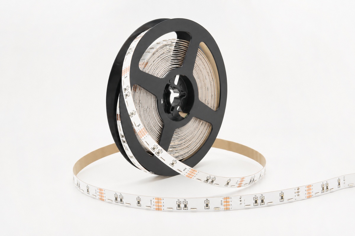
Browse our Single Color SMD LED Strips product specifications for exact W/m ratings across all density and voltage options.
Step 2: Apply the 80% Derating Rule
Power supplies are rated for their maximum continuous output under standard test conditions (typically 25°C ambient). In real installations, ambient temperatures are higher, ventilation is often restricted, and the supply runs continuously rather than intermittently. Running any electronic power supply at 100% of its rated load under these conditions accelerates thermal degradation and reduces lifespan.
The 80% derating rule—load the power supply to no more than 80% of its rated maximum output—is the standard adopted by electrical engineers for continuous-duty applications.
Required PSU rating = Total raw load ÷ 0.80
360 W ÷ 0.80 = 450 W minimum
Select the next standard PSU size at or above 450 W—typically a 480 W or 500 W unit.
Insight: Why 80% derating doubles your power supply lifespan. The electrolytic capacitors inside switching power supplies are the primary life-limiting component. Their degradation follows the Arrhenius model: lifespan doubles for every 10°C reduction in operating temperature. A power supply running at 80% load operates approximately 15–20°C cooler than the same unit at 100% load. The practical consequence: a PSU rated for 50,000 hours at 25°C that runs at 100% load in a 45°C ambient environment may deliver only 15,000–20,000 hours of service. The same unit derated to 80% in the same environment may deliver 30,000–40,000 hours—often spanning the full design life of the installation without replacement.2
Step 3: Understand and Manage Voltage Drop
LED strip PCBs use copper traces to conduct current along the strip. Copper has a finite resistance—standard 1 oz copper traces on a 10 mm wide PCB have a combined resistance of approximately 0.3 Ω per metre per rail. As current flows along the strip, the resulting voltage drop causes the LEDs at the far end to operate at a lower voltage than those at the supply end. Since LED forward voltage and forward current are closely coupled, lower voltage means lower brightness.
Calculating Voltage Drop
Current draw per metre = W/m ÷ supply voltage
  14.4 W/m at 24V → 0.6 A/m

Total current for 10m run = 0.6 A/m × 10 m = 6 A

Voltage drop = total current × resistance per metre × run length
  = 6 A × 0.3 Ω/m × 10 m
  = 0.9 V drop at the far end

As a percentage: 0.9 V ÷ 24 V = 3.75% — borderline visible
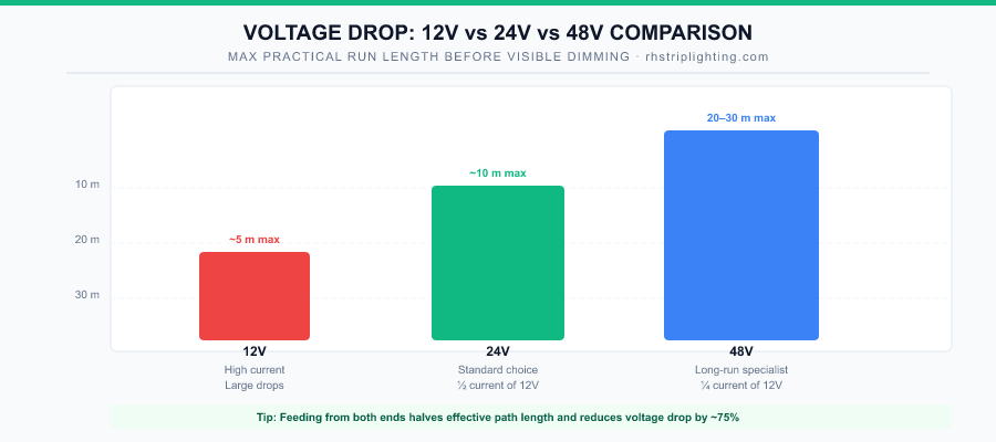
Insight: The visibility threshold is approximately 5%. Human visual perception of luminance differences on a uniform white surface is approximately 5% at comfortable viewing distances. A voltage drop producing more than a 5% reduction in drive current at the far end of a run will produce a brightness gradient visible to building occupants—not just to a photometer. At 24V, this limits a 14.4 W/m strip to approximately 12–13 m before feeding from both ends becomes necessary. At 12V with the same strip wattage, the limit is approximately 5–6 m.3
Voltage Drop Mitigation Strategies
| Strategy | Effect on Drop | Notes |
|---|---|---|
| Feed from both ends | Reduces drop by ~75% | Most practical for runs up to 2× the single-end limit |
| Use 24V instead of 12V | Reduces drop by 75% | Halves current; drop scales with current squared |
| Use 48V | Reduces drop by 94% vs 12V | 20–30 m single-end runs achievable; check product availability |
| Mid-run power injection | Effectively splits long run | Requires additional wiring run back to PSU |
| Specify 2 oz copper traces | Halves trace resistance | Available as premium option; verify with supplier |
Step 4: Match Voltage Precisely
LED strips are constant-voltage devices sensitive to supply voltage accuracy. Most 24V strips are designed to operate at 24V ±5%, meaning they accept 22.8–25.2V without performance impact. Outside this range:
- Supply voltage too high: LED drive current increases proportionally with voltage above the rated point, causing overtemperature, accelerated lumen depreciation, and potential early failure. A 24V strip driven at 26V operates roughly 20% above its thermal design point.
- Supply voltage too low: LEDs dim below their rated output. In color-changing strips, colour balance shifts as different colour channels have different forward voltage characteristics.
After installation, always measure supply voltage at the strip terminals—not at the power supply output. The difference between PSU output and strip terminals can be 0.5–2V depending on cable length and gauge. Most quality power supplies offer ±10% output voltage adjustment via a trim potentiometer; use it to set exactly the rated voltage at the strip terminals.
Step 5: Account for Inrush Current
Switching power supplies contain input capacitors that are discharged at power-up. The charging current spike—lasting typically 1–10 milliseconds—can be 5–20× the steady-state current draw. For a single 300W power supply, this inrush is manageable. For multiple supplies switched simultaneously from a single circuit breaker, the combined inrush can trip the breaker even though the steady-state load is within rating.
Mitigation options include:
- Soft-start power supplies: Built-in NTC thermistors or active inrush limiters that ramp up current over the first 50–100ms
- Staggered turn-on: Relay timers or scene controllers that bring zones up in sequence rather than simultaneously
- Correct breaker selection: Use Type D (high inrush tolerance) breakers for circuits feeding multiple LED drivers in parallel
Power Supply Type Selection
| Requirement | Specify |
|---|---|
| Indoor dry installation, Class 2 output | UL-listed enclosed constant voltage, Class 2 output |
| Outdoor or rain-exposed enclosure | IP65 or IP67 rated PSU, appropriate for enclosure temperature |
| Dimming (0-10V or DALI control) | Dimming-compatible PSU with matching protocol |
| High ambient temperature (>40°C) | Derate rated capacity by additional 20%; use convection-cooled unit |
| Long run requiring mid-run injection | Multiple smaller PSUs at injection points rather than one central large PSU |
| 24/7 continuous operation | Industrial-grade unit rated for 100,000+ hours; confirm capacitor life rating |
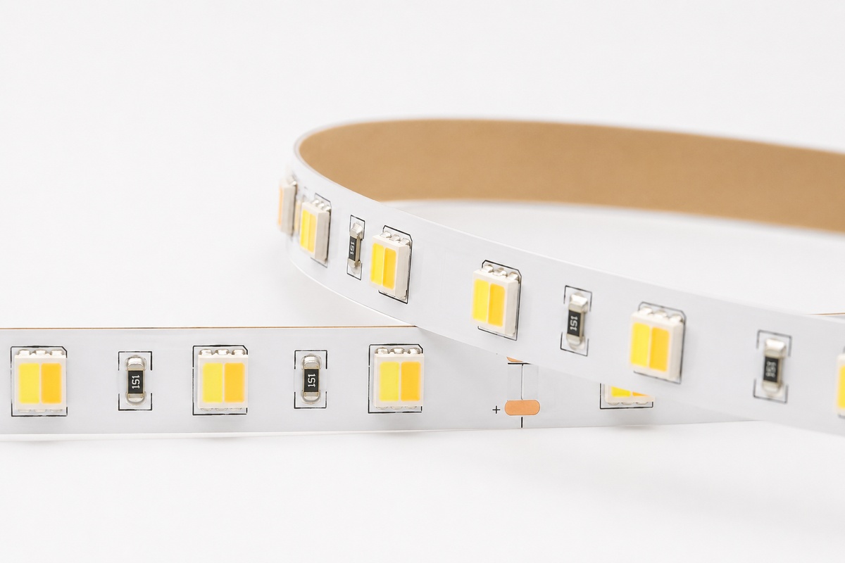
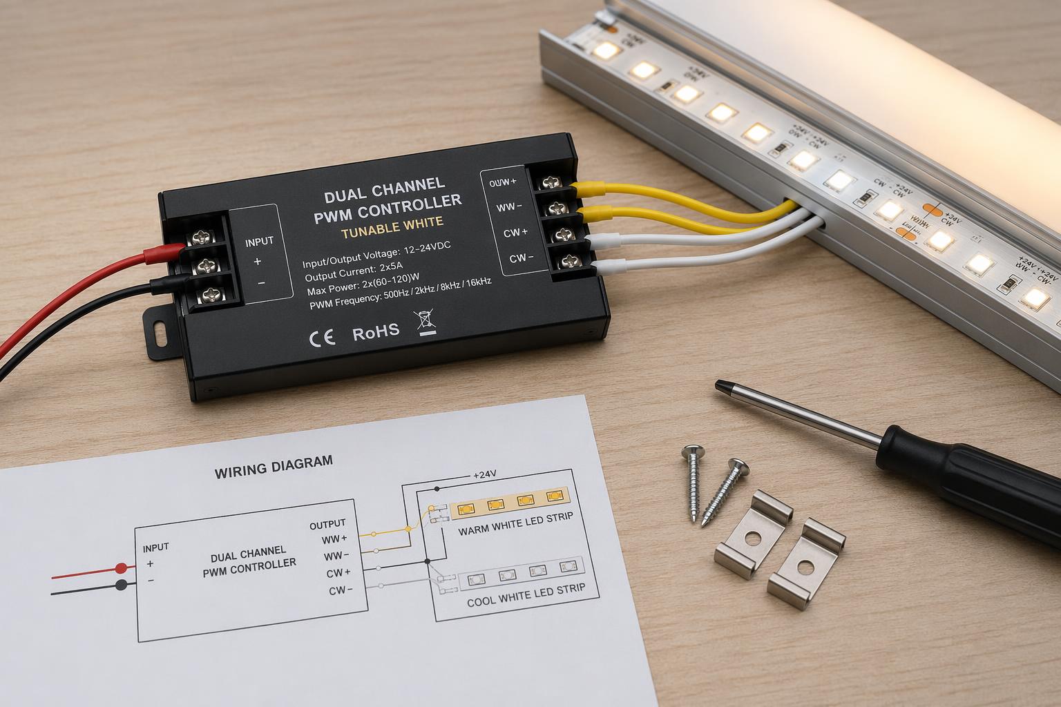
For dimming applications, our Tunable White SMD Strips and Tunable White COB Strips are engineered for compatibility with 0-10V and DALI dimming systems, with published dimming curve data available for control system programming.
Full Worked Example
Project: Hotel lobby perimeter cove, 24V single-color SMD
Strip specification: 14.4 W/m, 24V
Total run: 6 × 8m segments = 48m total

Step 1 — Raw load: 14.4 W/m × 48 m = 691.2 W
Step 2 — Derated load: 691.2 W ÷ 0.80 = 864 W minimum PSU
          → Specify two 500W PSUs (1,000W total, 69% load each)
Step 3 — Voltage drop check: 14.4W ÷ 24V = 0.6 A/m
          8m run: 0.6 × 8 × 0.3 = 1.44V → 6% — exceeds threshold
          → Feed each 8m segment from both ends
Step 4 — Verify 24V at strip terminals after installation
Step 5 — 2 × 500W units: inrush manageable if switched sequentially
FAQ
Can I use one large central PSU instead of multiple smaller ones?
Centralized power supplies reduce installed cost but create single points of failure: if the PSU fails, the entire installation goes dark. For critical hospitality or retail installations, zoned PSUs (one per area) are strongly preferable. They also simplify voltage drop management by reducing individual run lengths.
My strip spec says 12W/m but the reel feels warm at full load. Is the PSU oversized?
Strip temperature is primarily a function of wattage per metre and thermal management, not PSU sizing. A strip running warm means it needs better heatsinking—typically a wider aluminum profile with better thermal contact—not a smaller power supply. Never undersize the PSU to reduce strip temperature; the heat comes from the LEDs, not from the driver.
Do constant-current and constant-voltage LED strips need different PSUs?
Yes. The vast majority of LED strip lights are constant-voltage devices (12V or 24V). Constant-current drivers are used for individual LED module chains, not for strip lights. Using a constant-current driver on a constant-voltage strip will result in either over-driving or under-driving LEDs and likely premature failure.
How do I calculate the wire gauge needed for my runs?
Wire gauge selection follows the same current calculation: total amps × run length to the nearest injection point, referencing NEC Chapter 9 Table 9 or equivalent standard for your jurisdiction. For runs under 5 metres at less than 10A, 18AWG is typically sufficient. For longer runs or higher currents, upsize accordingly. Always verify with a licensed electrician for code compliance.
Recommended Products
Products for Correct Power Design
| Application | Product |
|---|---|
| High-output single-color cove | Single Color SMD (24V, up to 24W/m) |
| Tunable white with 0-10V dimming | Tunable White SMD |
| COB cove requiring low-voltage drop | Single Color COB (24V) |
| Outdoor with IP-rated PSU | Outdoor LED Strip Solutions |
All product specs include W/m rating, voltage, and current draw data required for complete power supply sizing. Contact our technical team for project-specific calculations.
References
- U.S. Department of Energy, LED Lighting Basics and System Design, Solid-State Lighting Program. ↩
- Arrhenius acceleration model for electrolytic capacitor thermal degradation; see also IPC-SM-785, Guidelines for Accelerated Reliability Testing of Surface Mount Solder Attachments, Section 3.4. ↩
- NFPA 70, National Electrical Code, Article 411: Lighting Systems Operating at 30 Volts or Less. ↩
Interested in Our LED Solutions?
Get professional consultation and customized LED lighting solutions for your projects. Contact our expert team today.
Related Articles
Tunable White LED Strips: The Complete Specification Guide for Architects and Lighting Designers
Tunable white LED strips blend warm and cool channels to produce dynamic CCT light. This guide covers dual-channel wiring, driver…
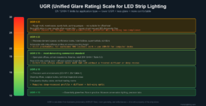
UGR and Glare Control in LED Strip Lighting: How to Specify for Visual Comfort in Commercial Spaces
UGR (Unified Glare Rating) is the most under-specified variable in commercial LED strip projects — yet it determines whether your…
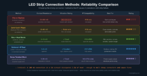
LED Strip Connectors and Soldering: Building Reliable Connections That Last
Connection failures are the #1 cause of LED strip callbacks. This guide compares clip connectors, lever-lock, and soldered joints by…