LED Strip Connectors and Soldering: Building Reliable Connections That Last
LED strip lights arrive on a reel. Your installation requires corners, extensions, right angles, and a power injection point 8 meters into the run. Every one of those junctions is a potential failure point — and the type of connection you make determines whether the installation lasts 10 years or 10 months.
Connection failures are the #1 cause of post-installation LED strip callbacks. They manifest as flicker at low loads, warm spots on the PCB that discolor the diffuser or trigger thermal protection, intermittent outages during vibration (in automotive or industrial applications), or visible dim sections that worsen over months as contact resistance grows through oxidation. Most of these failures were preventable with the right connection method and technique.
This guide covers every common LED strip connection method — clip connectors, solder joints, wire-to-board terminals, and IP-sealed assemblies — with honest performance data, and a step-by-step soldering technique reference for permanent installations.
Why Contact Resistance Is the Metric That Matters
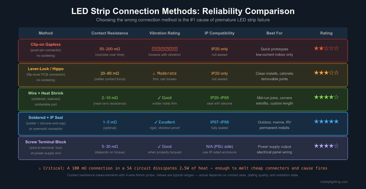
All connection methods can be evaluated on one primary metric: contact resistance measured in milliohms (mΩ). Contact resistance generates heat according to P = I²R. In a 5A circuit — typical for a 24V, 120W strip run — a 100 mΩ connector dissipates 2.5W of heat. A 200 mΩ connector (easily achieved by a cheap clip connector after 6 months of oxidation) dissipates 5W. That’s more heat than many LEDs on the strip itself, concentrated at a single point.
Insight: The failure curve for clip-on connectors is not linear — it’s exponential. In the first month, oxidation resistance adds perhaps 10 mΩ to the original contact resistance. By month 12 in a humid environment, the same connector may be at 150–300 mΩ. Because power dissipation scales with resistance (P = I²R), the connector heats up, which accelerates oxidation, which increases resistance further. This positive feedback loop explains why clip connectors rarely fail immediately — they fail six to eighteen months after installation.
The table below shows typical contact resistance ranges for each method. Target: keep total connection resistance below 20 mΩ per joint for any current above 3A.[1]
| Connection Method | Contact Resistance | Notes |
|---|---|---|
| Clip-on push-pin (gapless) | 50–200 mΩ | Rises significantly with oxidation |
| Lever-lock (flip-lever PCB connector) | 20–80 mΩ | Better contact force, more stable |
| Soldered wire + heat shrink | 2–15 mΩ | Near-zero when properly done |
| Soldered + silicone IP seal | 1–5 mΩ | Best performance, permanent |
| Screw terminal block | 5–30 mΩ | Depends on torque; must use proper torque spec |
Clip-On Connectors: When They’re Acceptable
Push-pin gapless connectors (commonly called “hippo” or “snap” connectors in the trade) are the fastest way to make an LED strip connection without tools. They are the dominant method in residential DIY installations and are widely sold with consumer strip kits.
Acceptable uses for clip connectors include:
- Prototyping and testing before committing to a final layout
- Low-current applications (<2A per channel) in dry indoor environments
- Temporary or seasonal installations (holiday lighting, display mockups)
- Under-cabinet strips in kitchen environments where access for replacement is easy
Not appropriate for:
- Any installation above 3A per channel
- Outdoor, humid, or temperature-cycling environments
- Any installation where access for maintenance is difficult
- Commercial projects with 3-year or longer warranty obligations
- Applications with vibration (automotive, RV, equipment panels)
Lever-Lock Connectors: The Professional No-Solder Option
Lever-lock connectors (brands include WAGO 221-series, Ideal In-Sure, and various LED-specific variants) use a spring-clamp mechanism that provides significantly better contact force than push-pin designs. The lever mechanism presses the strip’s copper pad against a tinned contact with consistent, repeatable force — unlike the spring-loaded pins in clip connectors, which lose tension over time.
For indoor commercial installations at moderate currents (2–5A), lever-lock connectors are the correct tool-free solution. They are field-serviceable (the lever releases without tools), produce repeatable connections, and have a useful life that typically matches the strip itself when used within rating.
Insight: The weakest point in any lever-lock connection is not the contact mechanism — it’s the strip pad itself. LED strip copper pads are typically 0.1–0.3mm thick and can delaminate from the PCB if the connector is inserted at an angle or forced onto a strip with silicone coating residue. Always clean the strip pad with IPA before inserting into a lever-lock connector, and verify the pad is seated flat and fully inserted before closing the lever.
Soldering: The Permanent, High-Reliability Method
For permanent installations, high-current runs, outdoor applications, and any project where long-term reliability matters more than installation speed, soldering is the correct method. A properly executed solder joint has contact resistance of 1–10 mΩ — 10 to 100 times lower than a clip connector — and does not degrade with oxidation over years of service.
The most common objection to soldering LED strips is the risk of heat damage to the LEDs. This concern is valid but manageable: LED junction temperature must not exceed 120°C (for most 5050 and 2835 chips), and the reflow solder temperature on the PCB pads is 183°C (63/37 tin-lead) or 217°C (lead-free). With proper technique, you apply heat for 2–3 seconds maximum — not long enough to conduct damaging heat to the adjacent LED chip through the PCB copper.
Required Equipment
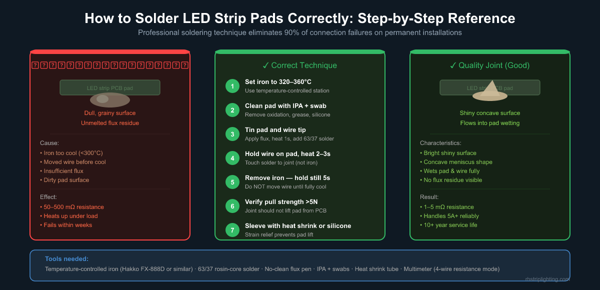
- Temperature-controlled soldering station set to 320–360°C (Hakko FX-888D, Weller WES51, or similar)
- 63/37 rosin-core solder (eutectic alloy — melts and freezes at the same temperature, minimizing cold joints)
- No-clean flux pen
- Isopropyl alcohol (IPA) 90%+ and cotton swabs for pad cleaning
- Heat shrink tubing (matched to wire diameter)
- Wire strippers and a small clamp or helping-hands tool
Step-by-Step Technique
- Clean the strip pad with IPA to remove silicone, grease, or oxidation. For silicone-coated (IP65) strips, carefully scrape off the silicone at the cut point with a craft knife before cleaning.
- Tin the pad: apply flux, heat the pad for 1 second, touch solder to the pad (not the iron tip). The solder should flow smoothly and wet the copper.
- Tin the wire end: strip 3–4mm insulation, twist strands tight, tin with solder so the wire is fully coated.
- Position the tinned wire on the tinned pad. Apply the iron tip to the joint, touching both wire and pad simultaneously, for 2–3 seconds. The pre-tinned solder on both surfaces melts and fuses.
- Remove the iron and hold the wire completely still for 5 seconds until the joint solidifies. Any movement while cooling produces a cold joint.
- Inspect: a quality joint has a shiny, smooth, concave surface. A cold joint looks dull, grainy, or convex.
- Slip pre-positioned heat shrink tubing over the joint and heat to shrink. This provides mechanical strain relief — without it, pad delamination from repeated flexing is common.
IP-Rated Connections: Sealing the Joint
For IP65, IP67, or IP68 outdoor installations, the connection point is the most vulnerable location for moisture ingress — not the strip body itself, which is factory-sealed. Maintaining IP rating through connection points requires:
Option A: Pre-assembled IP-rated connectors. These are factory-built connector assemblies with an overmolded or heat-shrink sealed junction. They are available for specific strip widths and pin counts. They provide the simplest field assembly but require the correct model number for your specific strip.
Option B: Solder + silicone end-cap. After soldering wires to the strip pads, fill a silicone tube end-cap with neutral-cure silicone, insert the connection point, and allow to cure for 24 hours. This achieves IP67 when done carefully. Do not use acetoxy-cure (acetic acid) silicone — the byproduct attacks tin and copper and increases contact resistance over time.
Option C: Solder + adhesive-lined heat shrink. Dual-wall heat shrink with internal adhesive lining flows into voids when heated, creating a near-waterproof seal. Rated for IP65 in most applications; not suitable for IP68 (submersion) without additional silicone encapsulation.
Wire Gauge: Matching Conductor to Current
A common mistake in LED strip wiring is using the same wire gauge throughout the installation regardless of current load. The minimum wire gauge for common LED strip currents (AWG, based on NEC 90°C insulated wire in free air):[2]
| Current | Minimum AWG | Typical Use Case |
|---|---|---|
| Up to 5A | AWG 20 | Short branch connections, single 5m run |
| 5–10A | AWG 18 | Parallel feeds, power injection |
| 10–15A | AWG 16 | Main supply lead from PSU to distribution |
| 15–20A | AWG 14 | High-wattage main supply runs |
For the connection from the LED strip’s PCB solder pads to the first junction, always use silicone-insulated wire (rated 200°C) rather than standard PVC wire. The high temperature from the iron tip will melt PVC insulation if it contacts it, whereas silicone insulation is unaffected.
Power Injection: When You Need It and How to Do It Right
Voltage drop along a strip run causes the LEDs farthest from the power supply to appear dimmer than those near the supply end — a visible banding effect on runs over 3–5 meters at high current. The solution is power injection: adding a second feed point from the power supply to the midpoint or far end of the strip.
Insight: Power injection does not reduce voltage drop within a strip segment — it reduces it by halving the effective run length from the PSU. A 10-meter run with end-injection still has a 5-meter segment at each feed point. For critical uniformity (museum, retail jewelry), calculate the voltage drop for each segment and specify the strip current density accordingly, or use 24V (which has 4× lower voltage drop than 12V for the same wattage).
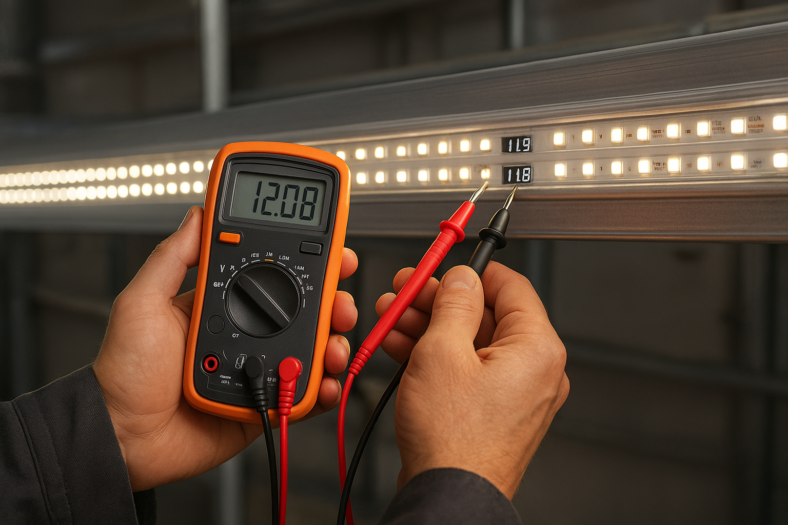
Injection points must be connected at the correct polarity. Reversed polarity at an injection point will create a short circuit between the new feed and the strip’s operating circuit. Before finalizing an injection point, always verify polarity with a multimeter before connecting power.
Frequently Asked Questions
Can I re-use a clip connector after disconnecting it?
Technically yes, but not recommended for permanent installations. Each insertion cycle slightly oxidizes the contact surfaces. A connector that was reliably 30 mΩ on first use may be 80 mΩ after 3 reconnections in a humid environment. For permanent installs, solder; for accessible test points, use a new clip connector.
Does the type of solder matter for LED strips?
Yes. Use 63/37 tin-lead rosin-core solder (eutectic alloy) if lead solder is permissible in your jurisdiction. It melts and resolidifies at exactly 183°C with no mushy transition zone, making it easier to achieve quality joints on the small LED strip pads. Lead-free solder (SAC305) melts at 217°C and has a wider pasty range, requiring slightly higher iron temperature and more technique precision.
How do I solder an IP65 silicone-coated LED strip?
Carefully score and peel back the silicone coating at the cut end using a craft knife. Cut perpendicular to the PCB to expose clean pad copper. Clean with IPA. Solder normally. After connection, re-seal with neutral-cure silicone or an adhesive-lined heat shrink sleeve to restore the moisture barrier.
What causes the LED strip pad to lift off the PCB when I solder?
Pad delamination usually results from one of three causes: excessive iron temperature (>380°C), too-long heat application (>5 seconds in one session), or mechanical stress while the solder is still hot. Always use a temperature-controlled station, limit each heat application to 3 seconds, and never pull or flex the wire while the joint is cooling.
Should I use liquid flux or rosin-core solder?
Rosin-core solder (flux embedded in the solder wire) is sufficient for most LED strip connections. Adding a flux pen gives a slightly cleaner joint on oxidized or pre-tinned pads. Avoid water-soluble flux unless you plan to wash the PCB afterward — water-soluble flux residue is corrosive if left in place.
Recommended Products
- Single Color SMD LED Strip Light — 24V, solderable copper pads, high-quality PCB for reliable connections
- Single Color COB LED Strip Light — 24V, continuous PCB for minimal solder point count per run
- Tunable White SMD LED Strip Light — 4-wire dual channel, pre-tinned solder pads, 24V
Footnotes
- Contact resistance specifications for electrical connectors are governed by IEC 61984 and MIL-C-26500. The 20 mΩ guideline for low-voltage DC connections is derived from connector industry thermal analysis at typical LED strip current levels. See: IEC Standards
- Wire ampacity ratings follow NEC Table 310.16 for copper conductors with 90°C insulation in conduit. Free-air ratings are approximately 20% higher. For LED strip low-voltage DC wiring in free air, these are conservative starting values. NFPA 70 Table 310.16
Interested in Our LED Solutions?
Get professional consultation and customized LED lighting solutions for your projects. Contact our expert team today.
Related Articles
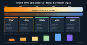
Tunable White LED Strips: The Complete Specification Guide for Architects and Lighting Designers
Tunable white LED strips blend warm and cool channels to produce dynamic CCT light. This guide covers dual-channel wiring, driver…
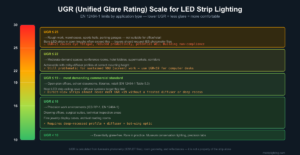
UGR and Glare Control in LED Strip Lighting: How to Specify for Visual Comfort in Commercial Spaces
UGR (Unified Glare Rating) is the most under-specified variable in commercial LED strip projects — yet it determines whether your…
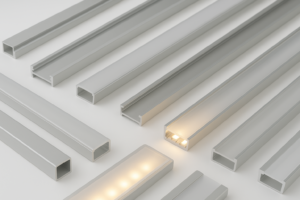
Why Aluminum Profiles and Extrusions Matter for LED Strip Installations
Bare LED strips may look cost-effective during procurement, but in commercial projects they often become the weak point of the…