LED Strip Lighting for Elevator Cabins and Lift Interiors
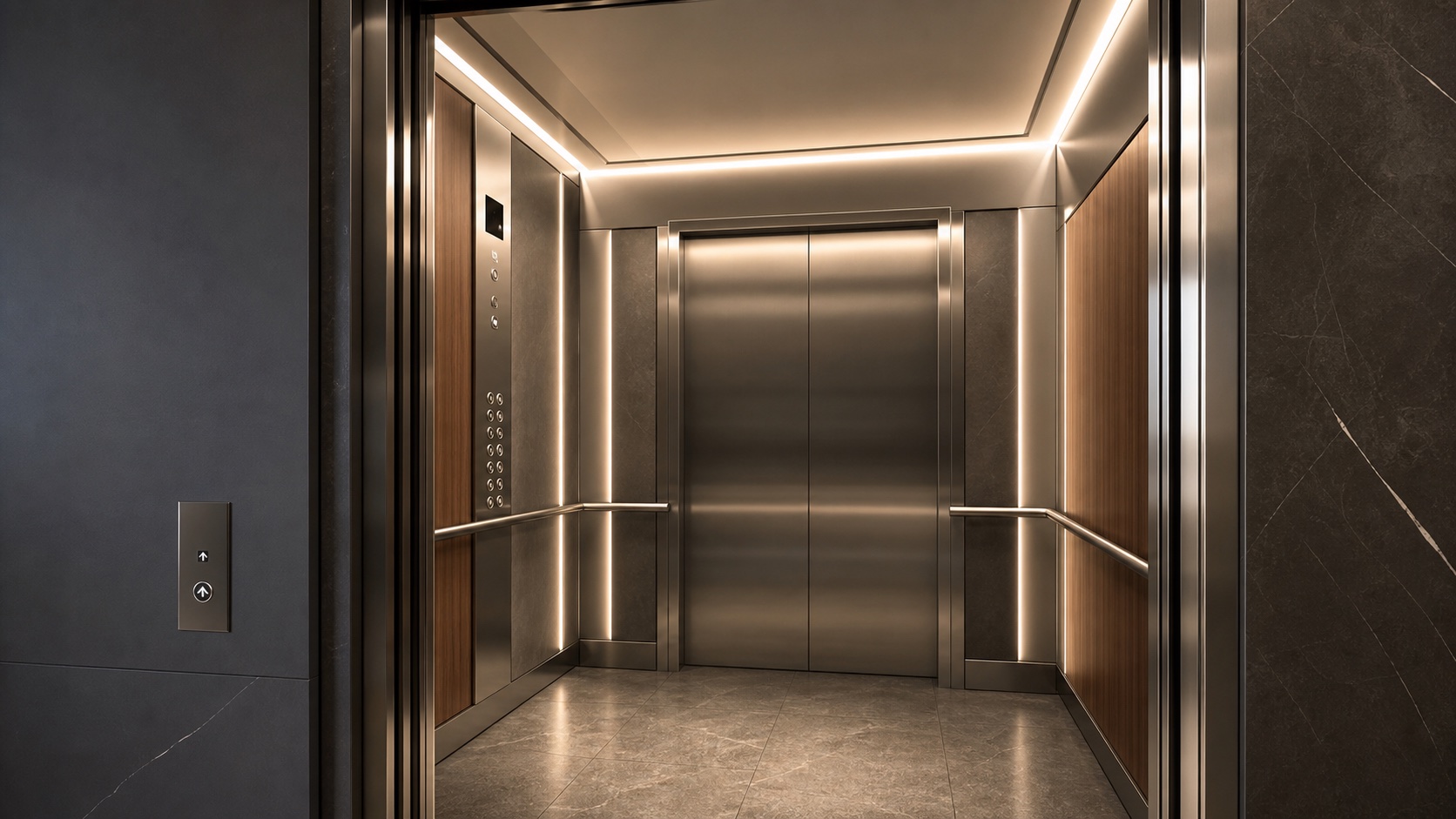
LED strip lighting can make an elevator cabin feel larger, calmer, and more architectural. But an elevator is not a small static room. It is moving equipment with door clearances, vibration, service panels, required controls, emergency functions, weight limits, inspection requirements, and a defined compliance path.
That changes the specification. The question is not only whether the light line is smooth or whether the CCT matches the lobby. The real question is whether the complete lighting assembly can remain safe, visible, quiet, serviceable, and consistent through thousands of trips and door cycles without interfering with the elevator’s required systems.
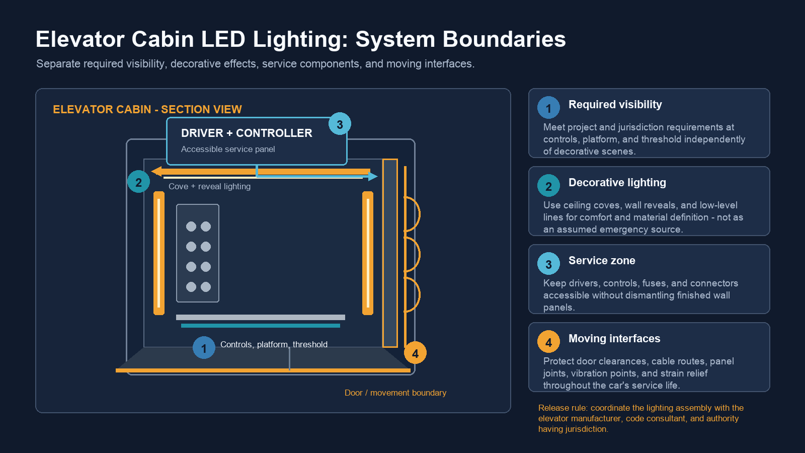
Start With Four System Boundaries
The ASME A17.1/CSA B44 Safety Code covers the design, construction, installation, operation, inspection, testing, maintenance, alteration, and repair of elevators and related conveyances.[1] An LED strip installation therefore cannot be evaluated only as an interior-design feature. It must be coordinated with the elevator manufacturer, project code consultant, electrical designer, and authority having jurisdiction.
This model prevents a visually attractive detail from quietly creating an operational problem. Each strip, profile, cable, driver, and controller should belong to a defined boundary, with a clear owner and acceptance test.
Required Light and Decorative Light Are Not the Same System
Decorative LED strips may contribute useful ambient illumination, but they should not automatically be treated as the sole source for required visibility or emergency operation. The project team must first identify which light levels and functions are required by the adopted code, elevator specification, and equipment listing.
For example, the U.S. Access Board’s ADA–IBC comparison identifies a minimum of 5 foot-candles, approximately 54 lux, at elevator car controls, the platform, car threshold, and landing sill.[2] This is a useful design reference, but the applicable jurisdiction, adopted code edition, and project requirements must be confirmed. A decorative cove that looks bright in a rendering may not deliver adequate light at the control panel or threshold.
Use separate acceptance criteria:
- required illuminance at controls, platform, threshold, and sill
- normal and emergency operating states
- visibility of indicators, tactile markings, instructions, and communication features
- decorative scene brightness and dimming range
- behavior when a decorative driver, controller, or strip segment fails
If the decorative strip participates in a required or emergency function, that role must be explicitly engineered and evaluated. Do not let it happen by accident because the main ceiling light was removed late in the interior-design process.
Design for Reflections Before Increasing Output
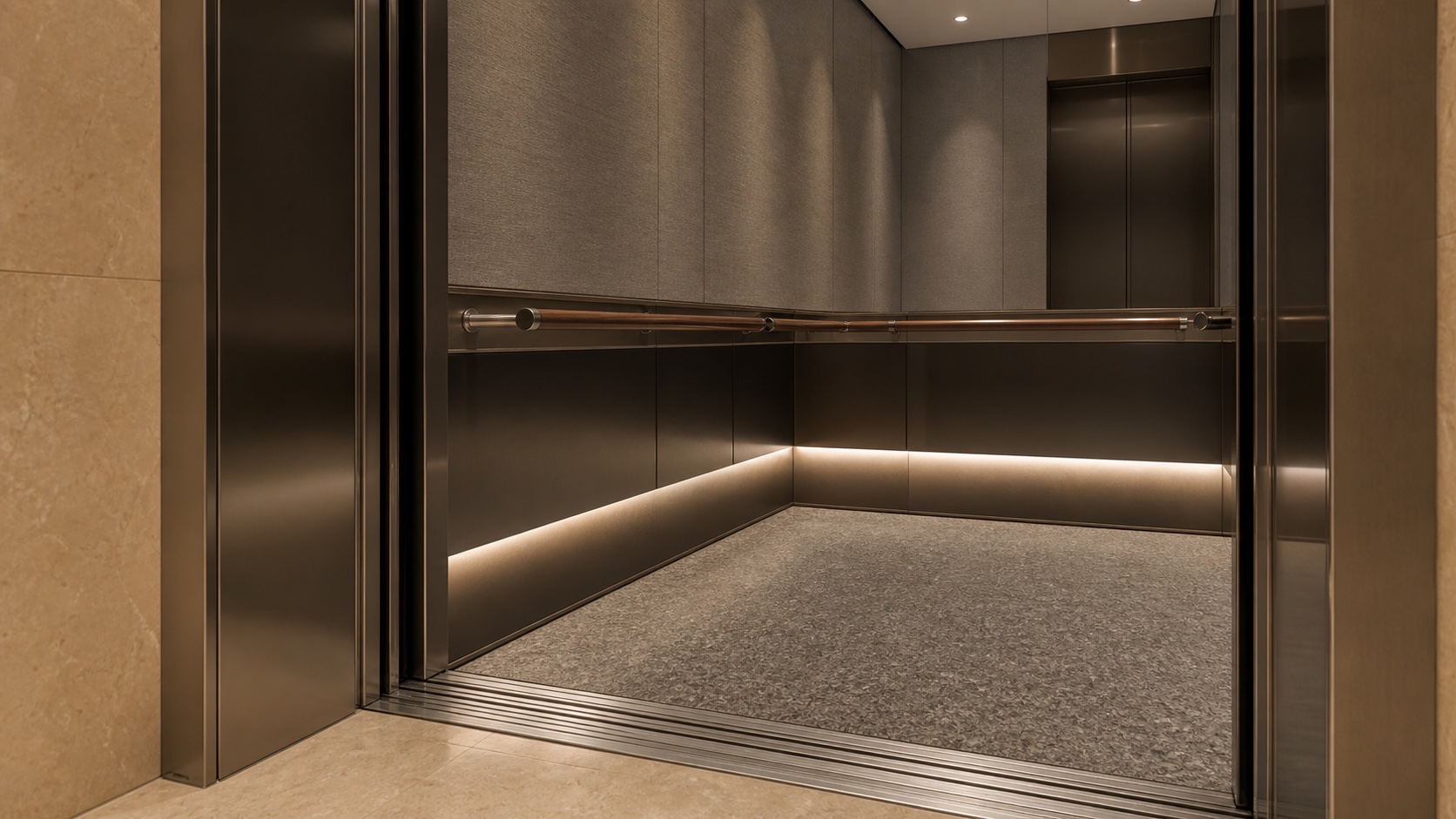
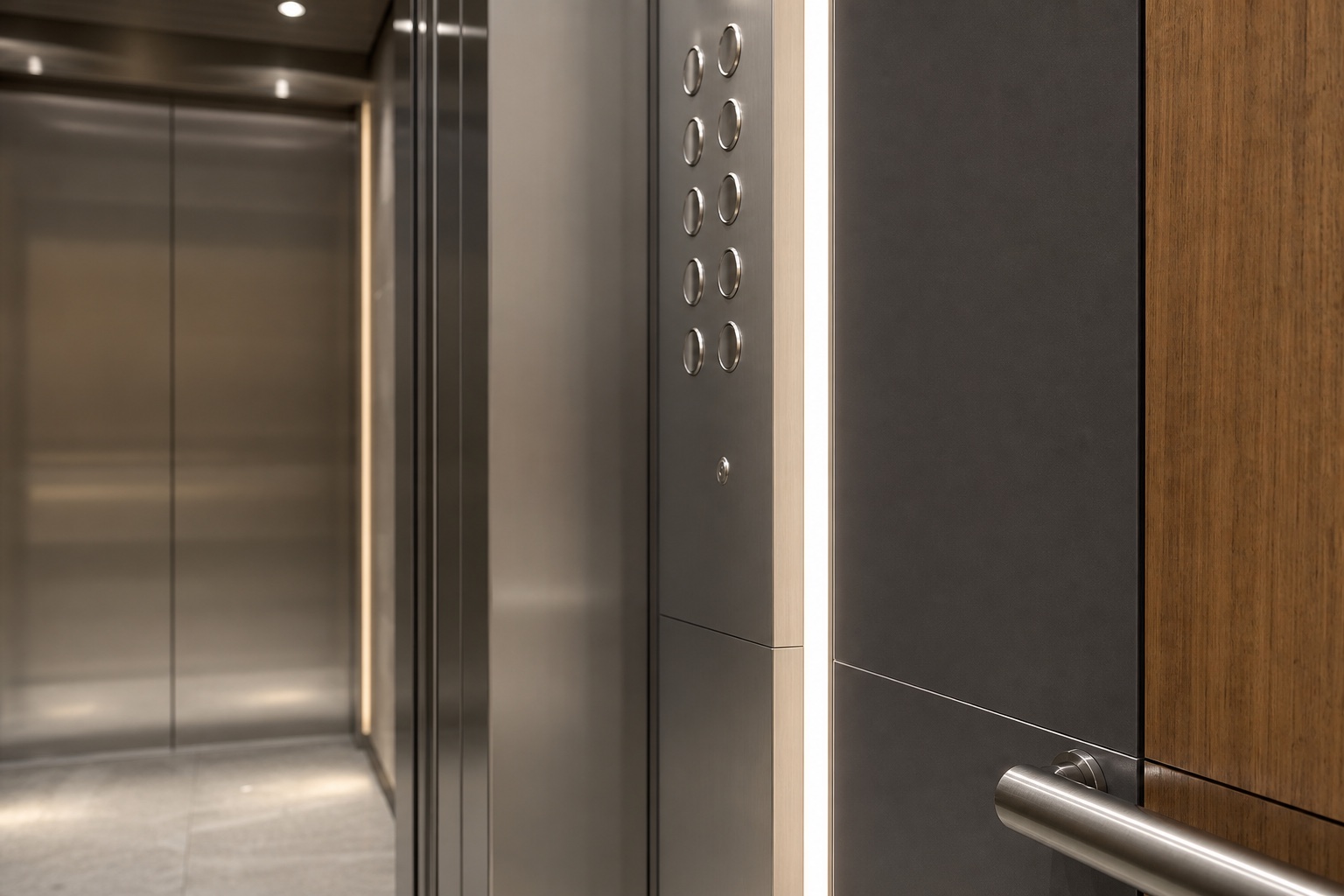
Elevator cabins are unusually reflective. Brushed stainless steel, mirror, polished stone, glass, high-gloss laminate, and dark coated panels can all reveal the light source from angles that are not obvious in a drawing. A strip can be hidden from a straight view yet appear as a bright duplicate in the opposite wall or door.
The common response is to reduce output after installation. That may lower glare but can also leave the control panel and threshold too dark. A better response is optical:
- recess the strip far enough that the diffuser is not visible from normal standing positions
- use profile depth and shielding to control the source angle
- aim wall-reveal light across matte material rather than directly at mirror or polished metal
- test both empty-cabin reflections and reflections with passengers present
- check the view from standing, wheelchair, and shorter-user eye levels
- evaluate the door in open and closed positions
Do not judge glare from photographs alone. Camera exposure can suppress bright source reflections that remain uncomfortable in person. Review a full-scale mockup with the actual metal grain, mirror position, diffuser, and trim depth.
Vibration Turns Small Installation Weaknesses Into Failures
An elevator car repeatedly starts, stops, levels, opens, closes, and travels. The movement may be gentle, but repeated cycling can expose weaknesses that do not appear during a static lighting test. Push connectors can loosen, unsupported cable can rub an edge, adhesive can creep, a diffuser can rattle, and a poorly retained profile can move against a finished panel.
For every lighting run, define:
- mechanical retention of the profile, not adhesive alone
- strain relief at strip leads, connectors, and driver terminals
- cable routing away from sharp edges, moving door hardware, and service-panel fasteners
- connector locking method and inspection access
- allowable bend at each cable transition
- how thermal expansion and panel movement are accommodated
Where a finished panel must be removable, the lighting connection should be deliberately serviceable. A technician should not have to cut hidden wires or pull a fragile solder joint to remove a decorative wall panel.
Keep Drivers Out of Sealed Decorative Cavities
Ceiling coves and wall reveals can be shallow, insulated, and surrounded by metal. Even an efficient LED system produces heat, and the driver adds its own losses. A cool-looking cabin may contain a warm ceiling plenum with little airflow.
Use an aluminum profile as part of the thermal path and verify the installed temperature at the planned operating level. Place drivers and controls in an approved, accessible service location where possible. Document the access method, fasteners, connector sequence, and replacement clearance before the finish panels are released.
Do not assume that an inaccessible driver is a maintenance issue only. Replacing it may require removing heavy ceiling panels, mirrors, or architectural finishes, increasing downtime and the risk of damage inside an operating building.
Choose the Product Family by the Detail
COB LED strip is often the best starting point for shallow ceiling coves and vertical reveals where the light line may be seen in reflection. RH Strip Lighting’s published COB range includes CRI above 90, multiple low-voltage choices, and very high LED density. The standard product-page construction is described as indoor IP20, so any special protection or cleaning requirement must be confirmed separately.
SMD LED strip offers broader voltage, density, color, and control configurations. It can work well in deeper profiles, wall washes, ceiling panels, and projects that need tunable white or color control. The result depends on the complete optic: LED spacing, profile depth, diffuser transmission, mounting distance, and reflection angle.
LED neon flex creates a self-diffused visible line and may suit robust wall outlines or architectural reveals where the luminous line itself is part of the design. RH’s listed range uses 24V and includes IP67/IP68 options. Inside an elevator, the larger section, weight, bend direction, mounting clips, and service access may matter more than waterproofing.
For related specification decisions, see RH’s guides to COB versus SMD LED strip, aluminum profiles and thermal management, and glare control in linear lighting.
Match the Lighting Hardware to the Compliance Path
Low voltage does not mean “outside the safety system.” UL Solutions lists standards including UL 1598 for luminaires, UL 8750 for LED equipment used in lighting products, and UL 2108 for low-voltage lighting systems.[3] Which standard or certification path applies depends on the product, system architecture, market, and how the lighting is integrated into the elevator.
The elevator manufacturer should review any change that affects wiring, ceiling assemblies, wall panels, access covers, fire behavior, equipment clearances, control interfaces, or emergency operation. A certified strip or driver does not by itself certify the completed cabin lighting assembly.
Confirm before production:
- applicable elevator, electrical, accessibility, fire, and lighting requirements
- normal and emergency power architecture
- approved mounting locations and service panels
- allowable materials, fasteners, cable types, connectors, and penetrations
- responsibility for inspection, testing, documentation, and field changes
Control Strategy Should Fail Predictably
Elevator cabin lighting may be switched, dimmed, scheduled, or integrated with building and elevator control logic. Tunable white and color scenes can support hospitality branding, but control complexity should not obscure the required operating state.
Document what happens when:
- the decorative controller loses communication
- power transfers between normal and emergency sources
- the car enters standby or energy-saving mode
- a single strip segment or driver fails
- service personnel bypass or replace a controller
- the cabin restarts after a power interruption
The safest failure behavior is project-specific, but it should be intentional, testable, and understood by the elevator and lighting teams.
Build a Six-State Mockup
A useful elevator lighting mockup includes the actual finish materials, mirror, door frame, control-panel surface, profile, diffuser, cable, driver, dimming method, access panel, and at least one representative corner or joint. A light box on a table cannot reveal the real reflection and maintenance problems.
- Static visual review. Measure required locations and review brightness, uniformity, reflections, CCT, and material rendering.
- Door-open and door-closed review. Check source visibility, threshold light, door reflections, and clearance at every operating position.
- Travel and vibration review. Listen for diffuser or panel noise and inspect cable, connector, profile, and fastener movement.
- Thermal soak. Run the final scene long enough to measure profile, driver, and service-cavity temperatures under realistic building conditions.
- Power-state review. Test normal operation, standby, restart, control loss, and the project’s emergency or backup state.
- Service simulation. Remove and reinstall the intended access panel, driver, connector, and strip segment without damaging finished surfaces.
| Acceptance item | Measure or inspect | Define before approval |
|---|---|---|
| Required visibility | Illuminance at controls, platform, threshold, sill, and other required points. | Target, minimum, measurement grid, operating state, and jurisdiction. |
| Visual comfort | Direct and reflected source visibility from representative eye levels. | Allowed bright-line exposure, dimming range, finish samples, and viewing positions. |
| Mechanical reliability | Profile, diffuser, cable, connector, fastener, strain relief, and panel movement. | Travel/door-cycle test, inspection points, and pass/fail conditions. |
| Thermal performance | Profile, strip, driver, and service-cavity temperatures. | Ambient condition, run time, measurement method, and product limits. |
| Serviceability | Access sequence, tools, disconnection, replacement, and restoration. | Maximum service time, replaceable unit, spare strategy, and finish protection. |
RFQ Checklist for Elevator Cabin LED Strip Lighting
- Elevator type, manufacturer, cabin drawings, code market, and responsible integrator
- Required illumination points and normal/emergency operating states
- Ceiling, wall, door, floor, mirror, handrail, and control-panel finish samples
- Lighting effect: cove, reveal, wall wash, low-level line, ceiling panel, or visible outline
- Voltage, wattage, CCT, CRI, dimming, control protocol, and scene behavior
- Profile, diffuser, shield, fastener, connector, cable, strain relief, and bend route
- Driver/controller location, access panel, replacement clearance, and spare strategy
- Door clearances, moving boundaries, vibration points, and panel-removal sequence
- Mockup states, measurement grid, thermal test, cycle test, and acceptance criteria
- Certification, inspection, documentation, and field-change responsibility
Specify the elevator lighting assembly, not only the strip
Share the cabin drawing, finish materials, lighting effect, required visibility points, voltage, control method, service-panel location, and project market. RH Strip Lighting can help identify a practical strip, profile, diffuser, wiring, and sample-test direction for coordination with the elevator team.
Request a Project RecommendationConclusion
LED strip lighting can transform an elevator cabin, but the best result is not the brightest or most decorative line. It is a controlled system that supports required visibility, respects reflective materials, survives movement, manages heat, remains serviceable, and fits the elevator’s compliance and inspection path.
Separate functional light from decorative light. Keep drivers and connectors accessible. Protect every moving interface. Test reflections on the real finishes, then test travel, heat, power states, and service access before release. That process turns a visual concept into an elevator lighting detail that can remain professional through years of operation.
References
- American Society of Mechanical Engineers, ASME A17.1 / CSA B44 Safety Code for Elevators and Escalators.
- U.S. Access Board, ADA and IBC Accessibility Standards Comparison, Chapter 4: Accessible Routes.
- UL Solutions, Lighting Safety Testing and Certification.
Request a Project or Trade Quote
Sourcing for an installation project, resale or OEM production? Share your requirements below. You can discuss project samples before committing to a bulk order.
Related Articles
LED Strip Lighting for Indoor Plant Walls: Accent Light or Grow Light?
Specify LED lighting for indoor plant walls without confusing visual brightness with plant needs. Review PPFD, DLI, controls, moisture, and…
LED Strip Lighting After a Power Outage: Designing a Reliable Restart
Plan LED strip power restoration beyond total watts. Review driver inrush, switching limits, restart scenes, and commissioning before project handover.
Why LED Strip Lights Buzz When Dimmed: A Guide for Quiet Spaces
Diagnose LED strip buzzing without guessing. Review drivers, PWM controls, mounting resonance, and low-level acoustic acceptance for quiet interiors.