
LED Strip Lighting in Historic Buildings: Design for Removal, Not Just Installation
The LED strip is discreet. The light is warm. The photographs look convincing. Yet the installation may still be wrong for a historic interior if replacing a failed section requires cutting painted plaster, lifting fragile timber, or peeling adhesive from a significant finish.
In an ordinary fit-out, a damaged mounting surface may be repaired or replaced. In a heritage project, that surface can be part of what the project exists to preserve. The lighting specification therefore needs to describe not only the finished effect, but also the future intervention.

This guide concerns decorative and supplementary LED strip lighting in historic interiors, including adapted hotels, visitor centres, shops, and public rooms. It is not an instruction to alter protected fabric. A conservation professional and qualified electrical designer should resolve the actual building conditions, approvals, and installation method. Emergency lighting and other required safety systems need their own compliant design.
Start With Significance, Not the Nearest Flat Surface
Before selecting tape width or watts per metre, identify which parts of the room have heritage significance. An old-looking wall, a later repair, and a newly built counter may need entirely different treatment. Appearance alone cannot establish what may be drilled, covered, cleaned, or removed.
The U.S. National Park Service’s rehabilitation standards emphasize retaining distinctive materials and features, and designing relevant new work so future removal does not impair the property’s essential form and integrity.[1] Applied to lighting procurement, that suggests a useful question: what remains after the equipment has gone?
Build an annotated room survey with three categories: protected or significant fabric, existing later work requiring assessment, and proposed new fit-out. These are project-management categories, not automatic permissions. Record the decision-maker for each proposed interface, including floors beneath freestanding equipment.
A narrow strip does not make the intervention small. The feed cable, driver, controller, protective equipment, and maintenance access may have a larger physical impact than the visible light source. Include them in the first drawing rather than adding them after the lighting effect has been approved.
Distinguish Removable, Replaceable, and Reversible
These words are often used as if they mean the same thing. For the project brief, separate the questions:
- Removable: can the equipment be detached using an identified procedure?
- Replaceable: can a failed component be exchanged without unnecessary dismantling of other work?
- Reversible in its effect on the building: after removal, what physical or visual change remains in the significant material?
A screw-fixed channel may be easy to remove but leave holes. Adhesive tape may peel away while lifting paint or leaving a darker contact line. A concealed installation may avoid visual clutter but require destructive access. None of those outcomes is resolved by calling the product “heritage-friendly.”
Ask for a removal method alongside the installation method. It should identify the tools, access route, component sequence, likely residues, and the person authorized to deal with unexpected resistance or fragile finishes. Do not promise complete reversibility where the evidence supports only easier servicing.
Put the Replaceable Layer on a Deliberately Chosen Support
A practical design exercise is to divide the assembly into three layers: the strip and optical components; the carrier and service route; and the building fabric. The objective is to keep routine lighting replacement within the first two layers wherever the approved design allows.
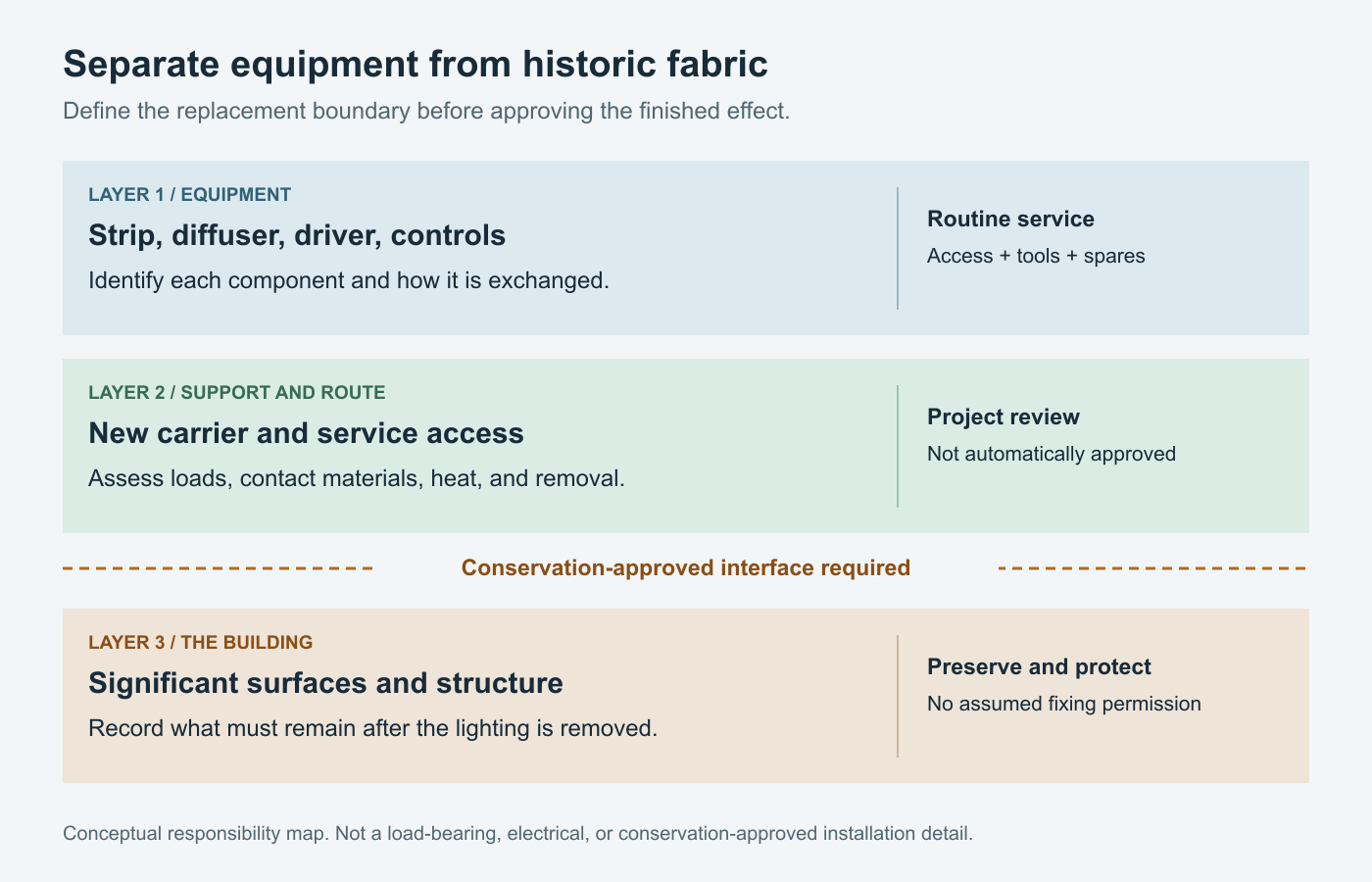
Possible candidates include a lighting channel incorporated into new display furniture, a purpose-designed removable rail, or a new service element already included in the conservation scheme. The support itself must be assessed: a freestanding unit can impose floor loads, obstruct movement, or rub a vulnerable surface. “Not screwed to the wall” is not a complete risk assessment.
Historic England’s building-services guidance stresses understanding the building before selecting routes and locations, minimizing intervention, and providing access for maintenance and eventual replacement.[2] Use that principle to compare complete installation options, not just competing strip prices.
For example, consider a reception console that already belongs to a new interior scheme. Keeping the strip, channel, and service compartment within that console may reduce the number of interfaces with the old room. It is a design option to assess, not permission to add furniture or run power across the floor.
Do Not Treat Adhesive as a Conservation Shortcut
“No drilling” can sound reassuring, but direct adhesive contact creates a different set of questions. What happens to the surface during application, aging, cleaning, and removal? Will a proposed primer or solvent change the finish? Can the substrate withstand the force needed to detach the tape?
The Canadian Conservation Institute warns against applying adhesives and tapes directly to collection objects because aging, residues, staining, and removal can cause problems.[3] That guidance concerns objects rather than a universal building specification. The relevant lesson here is to have a conservator assess contact with significant finishes, not to assume that a mounting-tape claim proves compatibility.
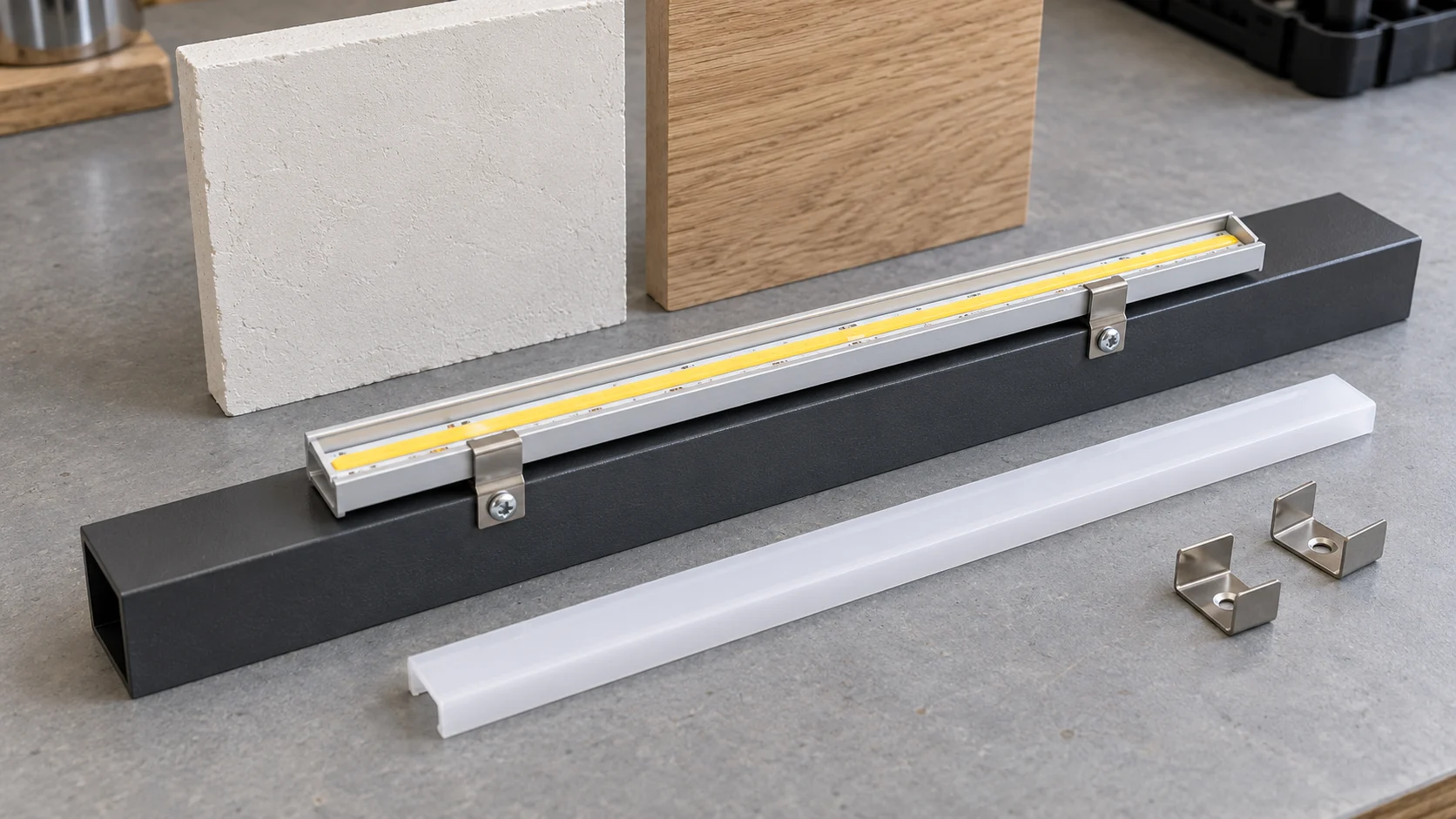
Keep ordinary adhesive-preparation instructions inside their proper scope. A procedure involving abrasion, degreasing, or primer on a new aluminium carrier must not be transferred automatically to historic plaster, varnished wood, stone, or decorative paint.
Test the proposed assembly on representative new mockup material first. Any test on original fabric needs explicit conservation direction, including location and evaluation. A short successful adhesion test cannot demonstrate years of aging or harmless removal. If the proposal depends on that assumption, change the interface rather than disguising the uncertainty.
Compare Cable Routes Before Demanding Complete Invisibility
An invisible cable route can be expensive in the wrong currency: lost material. Chasing a wall or opening a significant cornice to conceal a small feed may cause more harm than a carefully designed visible route or a different light position.
Historic England’s internal-lighting guidance advises careful fixing locations, use of existing routes where feasible, and avoidance of unnecessary new openings.[4] Existing does not mean automatically suitable. A route still needs inspection for condition, capacity, access, and electrical suitability; a historic hole is not permission to enlarge it.
Compare options on a marked-up drawing. For each one, show the entire route from supply to driver to strip, every transition between new and old work, and how each connection can be reached. Mark where the route relies on a surface or void that has not yet been inspected.
A remote driver may improve service access but creates a longer low-voltage cable run. The electrical designer must then check conductor sizing, voltage drop, protection, and manufacturer limits. Moving the driver is not a free solution to the conservation problem; it changes the electrical design. Our LED power-supply sizing guide provides background, but does not replace that site-specific calculation.
Approve the Lighting Effect Without Rewriting the Room
A modern strip can introduce a strong continuous line into a room whose visual character comes from separate historic fittings, irregular surfaces, or soft transitions. Before following every cornice with light, decide whether that line supports the interpretation of the room or overwhelms it.
Review the proposal with the lights off as well as on. Check whether the channel, clips, cable, and diffuser are distracting in daylight. At night, assess the actual viewing positions, reflections, and bright edges. A detail that disappears in a computer rendering may remain conspicuous from a doorway or seated position.
Select the product family after establishing the optical task. COB strip can be a candidate when a close-viewed line needs a continuous appearance; SMD strip can be assessed where the profile, diffusion, and setback provide the required result. Neither family guarantees low glare or suitability for a historic surface.
Use the real profile and diffuser in a mockup, rather than judging a bare strip. The installed-output guide explains why the completed assembly can differ from catalogue expectations. Where paintings, textiles, or sensitive furnishings are involved, obtain separate conservation advice on exposure; the museum-lighting guide addresses that different problem.
Make Heat and Access Visible in the Specification
Concealed does not mean thermally benign. ENERGY STAR explains that LEDs generate heat that must be managed, and that operating temperature affects performance and useful life.[5] A slim profile inside a closed detail should therefore be assessed as an assembly, not approved merely because the light source is LED.
Request the manufacturer’s mounting and thermal requirements for the proposed strip and driver. Record the operating load, ambient conditions, control state, and measurement locations used for the thermal review. A metal channel is not evidence that any chosen wattage will work in any enclosure.
Do not solve an overheating detail by improvising ventilation openings in historic joinery. Revisit output, location, carrier design, or equipment selection with the design team. Protection of adjacent finishes and safe electrical operation are separate requirements; passing one does not establish the other.
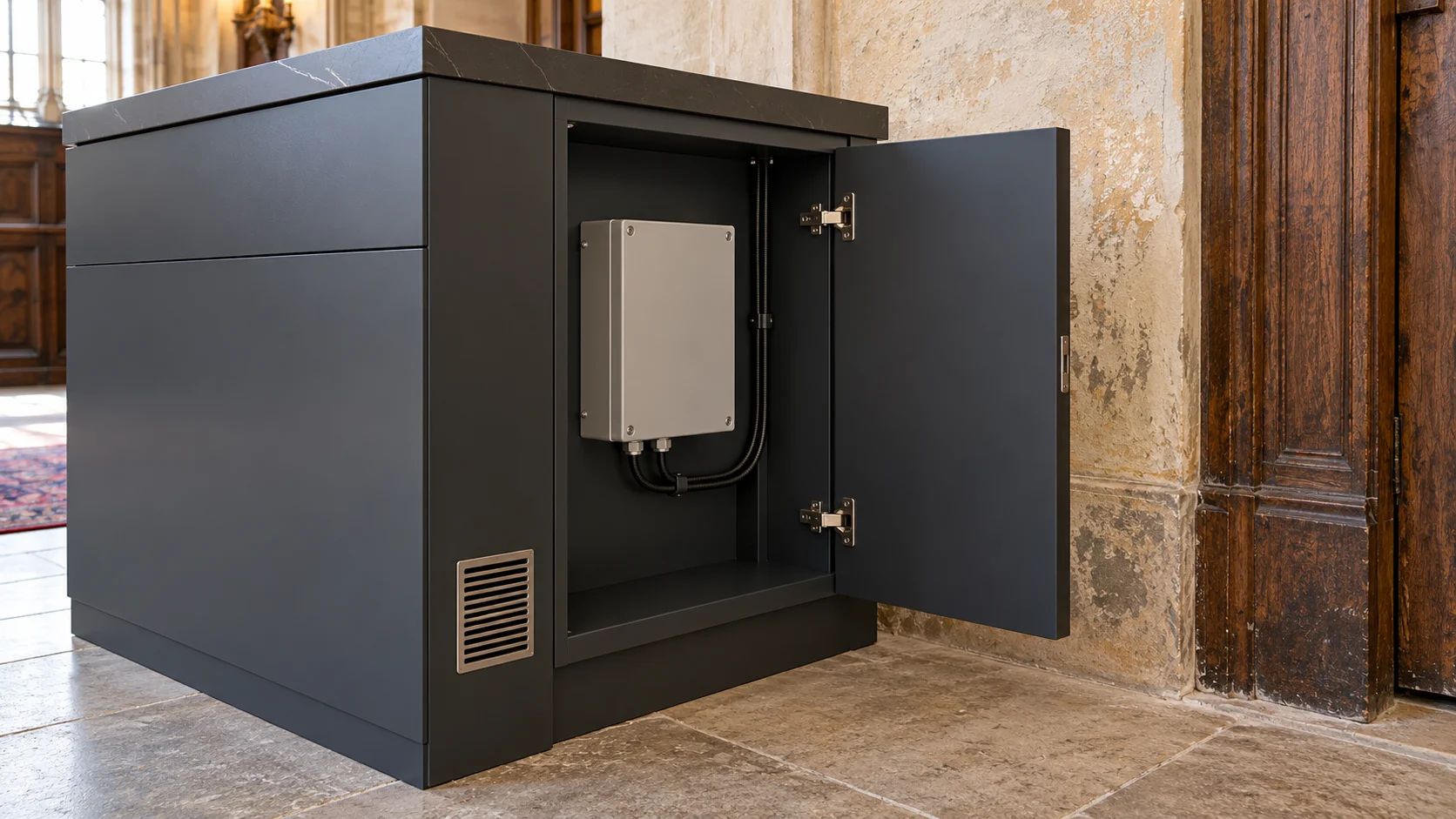
Then conduct an unpowered maintenance rehearsal on the mockup. Can the diffuser be removed without levering against the room finish? Can the strip or channel pass through the available opening? Is there clearance for hands and tools? Can a technician reach the driver without removing unrelated historic fittings?
Specify what is replaced together. Keeping a record of the strip, diffuser, profile, driver, and controls makes later substitutions more manageable. The existing-installation replacement guide covers compatibility checks, while reorder consistency matters when a replacement must match neighboring rooms.
Use an Intervention Schedule Alongside the Product Schedule
A conventional purchase schedule lists metres, watts, CCT, and quantities. Add an intervention schedule so the quotation does not leave the building interfaces undefined. The following is a proposed project record, not a conservation standard.
| Record | What to identify | Question before approval |
|---|---|---|
| Location and significance | Room, detail, finish, condition photographs, responsible reviewer. | Has the actual surface been assessed, rather than inferred from its appearance? |
| Mounting interface | Carrier, contact materials, fixing locations, load path, protection method. | What remains after removal, and who accepts that outcome? |
| Cable route | Supply, driver location, transitions, accessible joints, uninspected areas. | Does concealment depend on an unapproved opening or alteration? |
| Optical and thermal review | Actual assembly, approved scene, viewing positions, operating conditions. | Were the final diffuser, enclosure, and finishes included? |
| Replacement and removal | Component sequence, tools, access clearance, spare specification, stop conditions. | Can routine service stay within the approved replaceable layer? |
Agree hold points before procurement: acceptance of the route and interfaces, approval of the sample assembly, and approval to repeat the detail. A sample that looks right should not release the whole order while the driver location or fixing method remains unresolved.
Include two practical stop conditions in the contractor brief: an unexpected finish or void is found, or the approved component cannot be removed by the agreed method. The response should be to consult the responsible designer, not to enlarge an opening or use a stronger chemical without review.
Procure a Maintainable Detail, Not a Heritage Label
No single CCT, IP rating, adhesive brand, or LED construction makes a strip suitable for every historic building. Ask suppliers for evidence within their scope: dimensions, electrical characteristics, optical options, thermal requirements, control compatibility, and replacement availability. Building significance and permission to intervene remain with the project’s qualified advisers and relevant authorities.
References from England, the United States, and Canada below provide conservation and technical context. They are not interchangeable legal requirements, and this article does not establish what consent your project needs.
Plan the Strip Around the Approved Building Detail
Share the conservation-approved mounting concept, available space, strip lengths, driver location, desired effect, and control requirements with RH Strip Lighting. We can discuss product options for the proposed assembly; the project team should approve its building interfaces and validate the mockup before installation.
Discuss Your Lighting DetailThe strongest heritage lighting proposal answers a question beyond “How will it look on opening day?” It explains what the next technician can replace, what they must not disturb, and how the room can outlast the lighting system.
References
- U.S. National Park Service: Standards for Rehabilitation. Conservation principles concerning distinctive materials, compatible new work, and future removal; applicability depends on the project and jurisdiction.
- Historic England: Installing New Services. Survey, route planning, and access for maintenance and replacement in historic buildings.
- Canadian Conservation Institute: Products Used in Preventive Conservation, Technical Bulletin 32. Adhesives and tapes discussion concerns collection objects; used here to explain contact-material risks, not to approve building fixings.
- Historic England: Designing, Installing and Maintaining an Internal Lighting Scheme. Guidance on lighting briefs, fixings, existing routes, and maintenance.
- ENERGY STAR: Learn About LED Lighting. General LED thermal-management explanation; not a certification claim for any RH product.
Images are illustrative concepts. The intervention schedule and three-layer model are project-planning recommendations, not certified conservation details or measured product results.
Request a Project or Trade Quote
Sourcing for an installation project, resale or OEM production? Share your requirements below. You can discuss project samples before committing to a bulk order.
Related Articles
LED Strip Lighting for Retail Fitting Rooms: Face, Fabric, and Mirror Glare
Specify fitting-room LED strip lighting for faces, fabrics, and mirrors. Compare color reports, test reflected glare, and approve a repeatable…

LED Strip Lighting for Indoor Plant Walls: Accent Light or Grow Light?
Specify LED lighting for indoor plant walls without confusing visual brightness with plant needs. Review PPFD, DLI, controls, moisture, and…

LED Strip Lighting After a Power Outage: Designing a Reliable Restart
Plan LED strip power restoration beyond total watts. Review driver inrush, switching limits, restart scenes, and commissioning before project handover.