
LED Strip Lighting After a Power Outage: Designing a Reliable Restart
The reception cove works. The corridor responds to its sensor. Each display zone passes its own test. Yet after a building-wide power interruption, the installation trips a protective device, returns at the wrong brightness, or leaves several zones waiting for a controller to reconnect.
That is a different acceptance problem from ordinary dimming or power-supply sizing. The question is not only whether the lighting works once it is running. It is whether the complete system can return to an agreed operating state when power and control become available in a different order.

This guide addresses ordinary architectural LED strip systems for project buyers, integrators, and lighting designers. It is not a mains-wiring procedure or an emergency-lighting design. Circuit protection, fault investigation, switching equipment, and interruption tests require qualified personnel and an approved project plan. Never bypass protection or repeatedly reset a tripping circuit to force it to stay on.
1. Separate Running Load From Power-On Demand
Start with a correct steady-state load schedule, but do not stop there. LED strip output wattage describes the load delivered to the lighting. The AC supply must also account for driver losses and power factor. At energization, an electronic power supply can draw a brief input-current pulse that is very different from its normal running current.
MEAN WELL identifies simultaneous power-supply startup as a possible cause of upstream protection operating and distinguishes inrush from normal current.[1] The magnitude and duration depend on the equipment and test conditions. Do not apply a generic multiplier to every driver.
Illustrative calculation: twelve drivers each delivering 60W provide 720W in total. Assuming 90% efficiency and a power factor of 0.95 at that operating point, a 230V supply would carry approximately 720 ÷ (0.90 × 0.95 × 230) = 3.66A of steady-state input current. These are assumed values, not RH specifications, and this is not a circuit-rating recommendation.
The calculation says nothing about the input pulse at restart, contact switching capability, required circuit allowances, or fault protection. It also does not mean the strip’s DC current equals the driver’s AC current. Use actual model data and the installation rules applicable to the project.
For the first part of the calculation, use RH’s LED strip power-supply sizing guide. The restart review is an additional design check, not a substitute for correct sizing.
2. Ask for Peak, Duration, and the Approved Driver Count
An inrush figure without its conditions is incomplete. Ask for the input voltage, peak current, pulse-duration definition, relevant startup condition, and the manufacturer’s maximum driver count for the specified protective device. Preserve the exact driver suffix and revision, not just its wattage family.
Tridonic’s technical manual explains that circuit-breaker response depends on both current magnitude and duration, and that driver-count information belongs to a specific equipment combination.[2] Its example tables illustrate the method; they are not transferable ratings for RH installations or other drivers.
| Information to request | Why it matters | Insufficient substitute |
|---|---|---|
| Exact driver model and input conditions | Different designs can behave differently at the same output wattage. | “All are 100W drivers.” |
| Inrush peak and pulse-duration definition | The amplitude alone does not describe the event. | A single amperage copied without the test notes. |
| Maximum units on the specified protective device | Connects the driver data to the proposed circuit. | Total watts divided by the breaker label. |
| Other equipment sharing the restart | Lighting drivers may not be the only loads that return together. | A schedule limited to the strips visible in one room. |
| Permitted restart and switching conditions | A normal cold start does not document every interruption scenario. | One successful demonstration after a long shutdown. |
Do not sum headline peak values and treat the result as a complete protection study. Pulse shapes, timing, supply conditions, and the protective device’s behavior matter. Mixed-driver circuits need specific review; a count approved for one model is not automatically valid for a mixture.
Most importantly, do not change a breaker rating or trip characteristic merely to stop nuisance trips. The responsible electrical designer must preserve conductor protection, fault-clearing performance, and all applicable installation requirements. A circuit that stops tripping is not necessarily a correctly protected circuit.
3. Check the Switching Device as Well as the Breaker
The device that closes the circuit may be a relay in a building-control module, a contactor, a time switch, or another approved controller. Its suitability cannot be established from a general current label alone.
Finder distinguishes resistive-load ratings from lamp-load ratings and identifies inrush peak and specific energy as relevant to avoiding relay-contact sticking.[3] Ask for an LED or capacitive-load rating and any applicable driver-count limit for the exact switching product. Do not reinterpret a resistive rating as permission to switch the same nominal wattage of electronic drivers.
This creates two separate approval questions: will the protective device coordinate with the restart, and will the switching device tolerate its assigned load over the intended service duty? Passing one does not establish the other.
4. Distinguish a Fade From an Electrical Start Sequence
Imagine a lobby where the ceiling cove fades on first, the reception counter follows, and the corridor appears last. That may look like staged startup while every power supply has already received AC at the same instant. Delaying commands to the LED outputs does not, by itself, delay the initial charging event at each AC input.
A true input-energization sequence requires an appropriate power-distribution and switching design. An output soft-start function may serve a different purpose. Request a description of what the feature actually limits and at which point in the system it acts; the word soft-start alone is not enough.
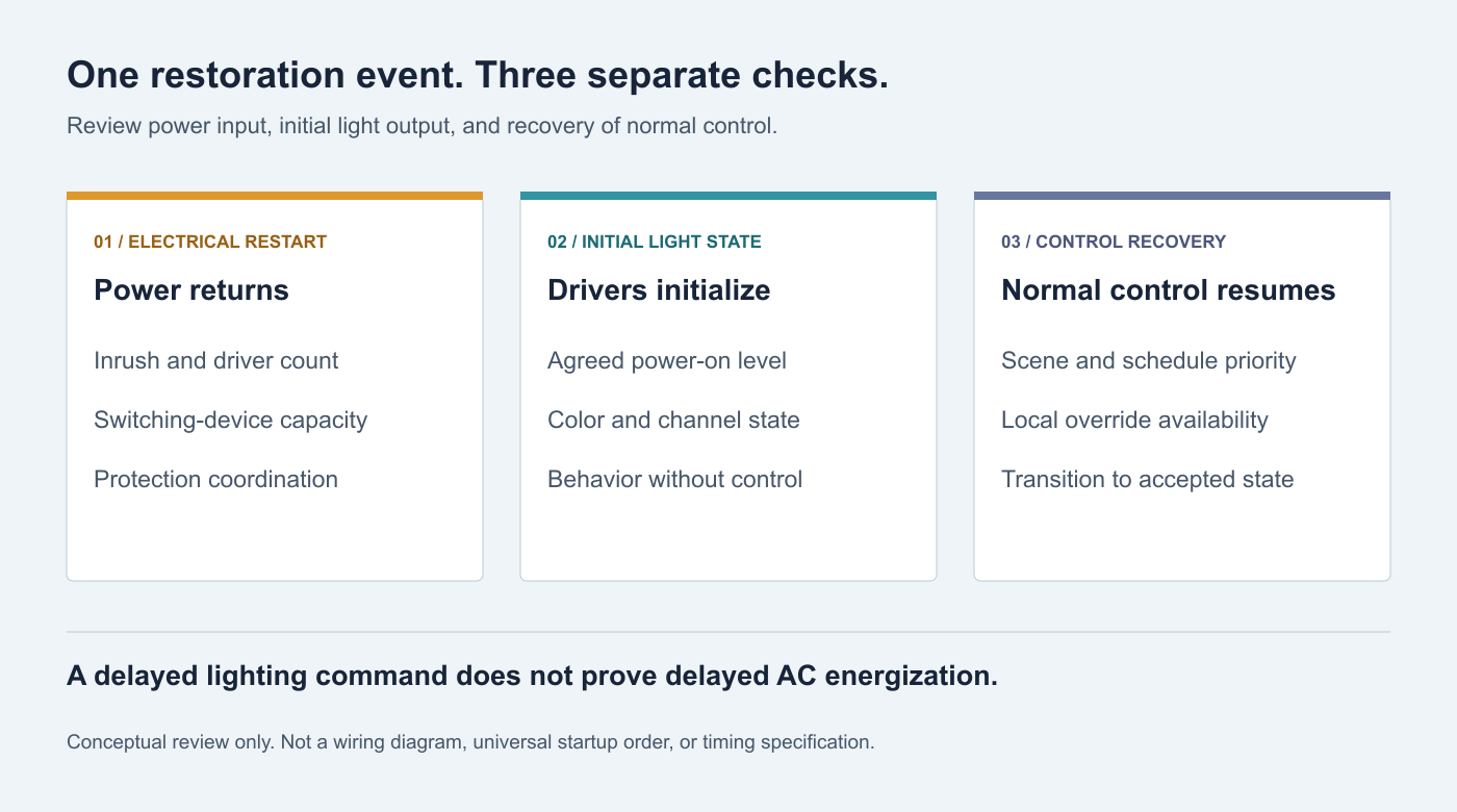
Consider a hypothetical layout with three rooms and four drivers in each. During normal use, room controls may operate separately. If all twelve drivers share an upstream supply restoration, the restart review must account for that common event. The room count is not proof of electrical staging.
There is a second trap: a sequence that depends on software may not operate as expected while the controller itself is rebooting. Record the initial state of the switching outputs and the behavior before configuration, network connections, and schedules are available. Verify those states with the integrator instead of assuming yesterday’s scene survives every restart.
5. Define What the Occupant Should See Before Control Recovers
Electrical restart can succeed while the visual result fails. A bedroom may return at full brightness, a reception desk may remain dark, or a tunable-white zone may briefly use an unwanted color setting. These outcomes need an agreed sequence, not an assumption that all equipment remembers its last command.
For DALI systems, Beckhoff’s documentation distinguishes the power-on level applied when control gear is energized from the system-failure level associated with a defined DALI-bus fault.[4] These are different conditions. A missing application command is not automatically the same event as a failed bus, and a particular device’s capabilities and settings must be verified.
For other control architectures, ask the equivalent questions: what happens before the controller is ready, when communication is unavailable, and when communication returns? Record brightness, channel mix where relevant, transition behavior, and the action needed to restore normal control.
Define the intended priority as well. Should a valid manual command override the returning schedule? Should a previously unoccupied room remain off? Which areas need local operation if the network is unavailable? The project team should decide these outcomes before configuration.
The DMX and DALI comparison helps frame protocol selection, while the tunable-white specification guide covers channel and color requirements. Neither a protocol label nor a smart-control badge proves the required recovery behavior.
Ordinary decorative lighting is not a replacement for required emergency or escape lighting. Do not use a fallback scene or a last-state memory feature as evidence of emergency-lighting compliance.
6. Choose Mitigation With a Defined Operating Limit
Potential design responses include a different driver, a revised circuit arrangement, an approved input-start sequence, or a suitable inrush-limiting device. Selection belongs to the system designer, who must review normal operation, startup, interruption behavior, thermal conditions, and protection together.
For example, MEAN WELL’s ICL-16 data sheet specifies more than its continuous current: it also includes permitted capacitive load, limiting behavior, and operating conditions.[5] It demonstrates why an inrush limiter is a rated device to coordinate, not an unlimited accessory. This reference is not a recommendation to add that model to every strip installation.
Do not add improvised resistors, thermistors, or bypass relays to a mains circuit. Do not assume a surge-protection device performs the same function as an inrush limiter. Ask the supplier to identify the function and validated limits of the proposed solution.
Any mitigation that introduces timing must have an agreed basis. Specify who determines delays, what happens after a short interruption, and how the system returns if the control processor is still starting. Do not assign an arbitrary delay from another project’s settings.
Replacing a driver also changes more than startup behavior. Recheck output compatibility, dimming, thermal performance, acoustics, and service access using the replacement compatibility guide and the quiet-space dimming guide.
7. Commission the Restart, Not Only the Scene Buttons
Agree a controlled test plan with the electrical and controls teams before handover. Tests involving supply interruption must use approved methods, authorized personnel, and a planned outage window. Do not interrupt unrelated critical systems or repeatedly cycle power as a diagnostic shortcut.
The following schedule is a project-planning tool, not a formal test standard. The designer should select safe scenarios, durations, repetition limits, and pass criteria for the actual equipment.
| Scenario | Observe and record | Acceptance question |
|---|---|---|
| Normal scene command with drivers already energized | Light level, fade, group response, and control status. | Does ordinary control work as specified? |
| Approved full-system power restoration | Protective-device status, which groups return, and initial visible state. | Can the complete installation restart, not just individual zones? |
| Equipment-permitted short interruption | Recovery behavior and any difference from the planned cold-start test. | Does the agreed interruption case recover correctly? |
| Driver power available before control is ready | Initial brightness/color and transition to normal operation. | Is the temporary state acceptable? |
| Approved control-availability fault simulation | Fallback behavior, local operation, and restoration of control. | Are control failure and power restoration handled separately? |
| Final connected configuration | Driver count, models, shared loads, and installed settings. | Does the tested setup match the delivered installation? |

If protection operates, record which device operated, the event sequence, and the affected equipment, then stop for investigation. A trip alone does not prove inrush; wiring faults, leakage-related protection, overload, and equipment failure require different assessment. Do not treat a later successful reset as clearance of the original problem.
A brief pulse may not be captured by an instrument intended for ordinary steady readings. Where measurement is needed, qualified personnel should select suitable equipment and a safe method. Buyers should request a report containing the relevant conditions, not attempt live measurements themselves.
8. Make Restart Behavior Part of the Handover Package
Keep the approved driver and switching-device schedule, circuit assignments, control-group mapping, configuration backup, and restart acceptance record together. Identify who owns changes and which replacements require retesting.
A useful handover states the expected initial scene, the allowed recovery sequence, local operation during control unavailability, and the escalation path after a trip. A screenshot of the final app scene is not enough to reconstruct the electrical or control settings.
For repeat projects, a successful mockup is a reference configuration, not permission to substitute any same-wattage driver. Keep the operating requirements in the LED strip RFQ and require proposed changes to be reviewed before delivery.
Selecting the Lighting Components
COB and SMD choices determine aspects of the optical assembly, but neither label establishes acceptable restart behavior. Choose the strip for its output, color, profile, and application; then coordinate the power and control equipment for the complete installation.
Include restart requirements before the order
Send RH Strip Lighting your zone layout, strip lengths, proposed power and control models, and expected restoration behavior. Request model-specific information and samples where available. Electrical protection and whole-system commissioning remain the responsibility of the qualified project team; no untested combination should be treated as pre-approved.
Discuss a Multi-Zone Lighting ProjectA reliable installation is not only one that looks right after a successful startup. It is one whose power path, switching devices, control settings, and recovery behavior have been checked together before the next interruption tests them unexpectedly.
References
- MEAN WELL FAQ: Inrush Current and Power Factor. Input startup demand and steady-state power relationships. Use the actual model data rather than generic example values.
- Tridonic: DC-String Product Manual, section 6.4. Technical explanation of circuit-breaker loading and pulse magnitude/duration. Historical product examples are not current equipment-selection tables for this project.
- Finder: General Technical Information. Contact ratings, lamp loads, and inrush current/specific energy. Exact product ratings must be checked separately.
- Beckhoff: DALI Variables. Distinguishes powerOnLevel from systemFailureLevel; verify supported behavior in the selected control gear.
- MEAN WELL: ICL-16R/16L Data Sheet. Example of an inrush limiter with defined current, capacitive-load, and operating limits; not a universal product recommendation.
Request a Project or Trade Quote
Sourcing for an installation project, resale or OEM production? Share your requirements below. You can discuss project samples before committing to a bulk order.
Related Articles

Why LED Strip Lights Buzz When Dimmed: A Guide for Quiet Spaces
Diagnose LED strip buzzing without guessing. Review drivers, PWM controls, mounting resonance, and low-level acoustic acceptance for quiet interiors.

LED Strip Lighting for Modular Retail Shelves: Design for Reconfiguration
Specify modular shelf lighting beyond driver wattage. Check shared-feed current, connector durability, cable movement, controls, and approved configurations.

LED Strip Lighting for Wine Cellars and Bottle Displays: Beyond Warm White
Design wine-display LED lighting around spectrum, exposure time, label visibility, and heat. Learn why warm white and low UV are…