
Replacing LED Strips in Existing Installations: Compatibility, Color Matching, and Retrofit Checks
A short dark section appears in a hotel cove, a display cabinet, or a reception desk. The maintenance request sounds simple: replace the failed LED tape without disturbing the finished joinery. The old strip says 24V and 3000K, so a new roll with the same labels seems like an equivalent replacement.
Those two numbers are only the beginning. The replacement may draw more current, have incompatible control wiring, leave a dark gap at the end of the channel, or look conspicuously different beside the surviving LEDs. A successful repair preserves the behavior of the installed system, not just its ability to switch on.

1. Confirm What Failed Before Specifying What to Replace
A dim end, intermittent joint, discolored cover, and failed LED segment can look similar from floor level. Record the symptom, affected length, operating scene, and whether neighboring runs behave normally. Have a qualified person establish the fault and its cause before ordering replacement tape. RH’s LED strip diagnostic checklist covers the fault-finding stage; this guide addresses the replacement decision after that diagnosis.
Do not use a new strip to compensate for an unresolved overheated connection, moisture ingress, failing driver, or unsuitable mounting surface. Otherwise, the repair repeats the conditions that caused the failure. Keep the removed components until the cause and replacement specification are documented.
Scope and safety: This guide concerns specification of conventional low-voltage LED tape systems. It is not a live electrical testing procedure. Isolate supplies before handling components; mains-side work, damaged wiring, unknown systems, and changes to protective arrangements require qualified personnel. Emergency lighting, hazardous locations, and manufacturer-specific luminaires need their own approved service procedures.
2. Recover the Installed Specification, Not Just the Purchase Description
Photograph the driver and controller labels, strip markings, connector pinout, end terminations, and profile cross-section. Find the original drawings or invoice, then check them against what is actually installed. A project may contain substitutions or several similar-looking products.
| System layer | Information to recover | Why an apparent match can fail |
|---|---|---|
| Power source | Exact model, output mode, voltage or current, allowable load, dimming method, installation conditions. | A voltage number on a constant-current driver’s operating range is not a fixed-voltage output specification. |
| Controller and feeds | Output type, per-channel and total current limits, conductor arrangement, feed locations. | The driver can have spare capacity while a controller channel or connector does not. |
| LED tape | Voltage, circuit type, W/m, width, cut increment, color channels, polarity, environmental construction. | Equal voltage and width do not establish equal load or wiring compatibility. |
| Profile and optics | Usable mounting width, cover clearance, diffuser condition, connector space, end gaps. | The tape may fit while its termination or emitting surface does not. |
| Visual reference | Surviving run, finish colors, normal scenes, operating history, approved appearance. | The original nominal CCT does not describe the present aged appearance. |
If the original model cannot be identified, describe the job as an engineered replacement, not a confirmed like-for-like swap. An offcut and clear label photographs are more useful than a request for “something similar.” Do not infer voltage from LED package size or pin count.
3. Match the Electrical Architecture Before Comparing Brightness
Start with the supply mode. Conventional resistor-limited 24V tape requires an appropriate constant-voltage supply. An LED board designed for constant-current operation requires its specified current and a compatible driver operating range. Some constant-voltage strips contain local current-regulating electronics, so the presence of an IC does not by itself mean that an external constant-current driver is required.
MEAN WELL distinguishes simple LED loads from resistor-equipped strips and shows that driver output behavior matters when dimming the latter.[1] Read the actual strip and driver documentation together. A driver marked with a range that includes 24V is not automatically a substitute for a 24V constant-voltage supply.
For single-color, tunable-white, RGB, and RGBW tape, verify terminal functions rather than matching connector shape. Channel order and common conductor arrangement must agree with the controller. Addressable tape adds chipset, signal protocol, direction, and controller configuration requirements; it should not be substituted for analog tape as a routine repair.
Use the constant-current versus constant-voltage guide to clarify terminology, then approve the exact combination rather than the product-family name.
4. Recalculate the Load at Every Bottleneck
The nominal DC load calculation is straightforward: power = installed length × W/m, and current = power ÷ supply voltage. The decision is not complete until that current is checked against the driver, controller, relevant channels, connectors, and wiring arrangement.
Consider an illustrative 8 m single-color installation at 24V. The old tape is rated 9.6 W/m. Its documented system uses a 100W driver and a controller with a 4A total output limit. Assume those are the applicable limits under the installation conditions; real products may require additional derating.
| Replacement scope | Nominal DC load | Nominal current at 24V | Initial finding |
|---|---|---|---|
| Original: 8 m at 9.6 W/m | 76.8 W | 3.2 A | Below both stated limits. |
| Replace 1 m with 14.4 W/m; retain 7 m | 81.6 W | 3.4 A | Total passes this arithmetic check; local load and visual match still need review. |
| Replace all 8 m with 14.4 W/m | 115.2 W | 4.8 A | Exceeds both the 100W driver and 4A controller limits. |
These are calculations, not RH product ratings or approval of a mixed-strip circuit. The one-meter replacement increases that section’s nominal load from 9.6W to 14.4W, a 50% increase, even though total circuit current rises by only 6.25%. A satisfactory total does not demonstrate an acceptable local heat path.
Check multi-channel products against both per-channel and combined limits in every permitted scene. Include the actual feed topology and loaded voltage at remote points in commissioning. Do not increase supply voltage to conceal a dim end. See RH’s driver sizing guide for the power-budget stage.
5. Check Cut Length and Terminations Inside the Real Channel
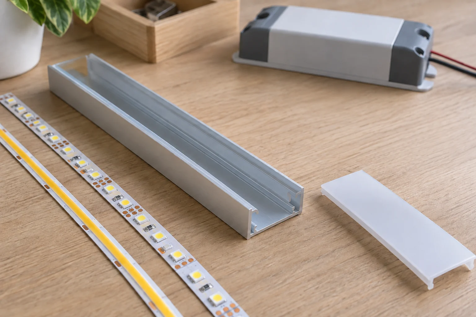
Measure the usable flat mounting surface, not just the profile’s outer width. Include encapsulation, solder pads, lead exit, connector height, and space to remove the diffuser later. A slightly narrower strip can still fail to fit if the connector fouls the cover or a thicker emitting surface changes optical clearance.
Cut increments can make an otherwise suitable product impractical. If the verified available tape length is 970 mm, a product cuttable every 50 mm offers a maximum 950 mm segment within that space; a 25 mm increment also stops at 950 mm, while a 10 mm increment permits 970 mm. Then subtract any required termination clearance. These are geometric examples, not instructions to cut outside marked positions.
Approve where any unlit gap will appear. Do not create an improvised folded end to consume excess length. Respect the product’s permitted bend direction and radius, preserve required insulation, and use documented termination methods. Retained channels must be clean, sound, and suitable for the new tape’s mounting and thermal requirements. Consult the profile selection guide and connection reliability guide when assessing reuse.
6. Match the Installed Appearance, Not Only the CCT Label
DOE explains that correlated color temperature compresses color-coordinate information and that LED systems can change color before they stop producing light.[2] Consequently, a new 3000K tape can be correctly specified yet visibly different from a surviving 3000K run. Brightness and diffuser condition add further differences.
Compare the proposed replacement in the retained profile behind the intended diffuser, beside the actual surviving installation. Review the usual viewing positions and room scenes after output stabilizes. A bare-tape photograph on a workbench cannot establish the final match.
A tighter bin specification improves consistency among new products; it does not promise a match to aged lighting from an unknown batch. Use RH’s color-binning guide for new-product control, but approve the repair with a physical sample.

Where practical, compare the old and new sources through the same sound diffuser, then compare the covers using the same source. This helps distinguish an LED mismatch from a cover-related change. Replace brittle, damaged, or unsuitable optics rather than treating their appearance as a target to reproduce.
7. Choose the Replacement Boundary Deliberately
A joint is most noticeable when old and new light illuminate the same uninterrupted surface. A room corner, opaque divider, cabinet bay, or existing independent zone may provide a more acceptable transition. That makes the smallest sensible replacement a visual unit, which is not necessarily the same as the failed electrical segment.
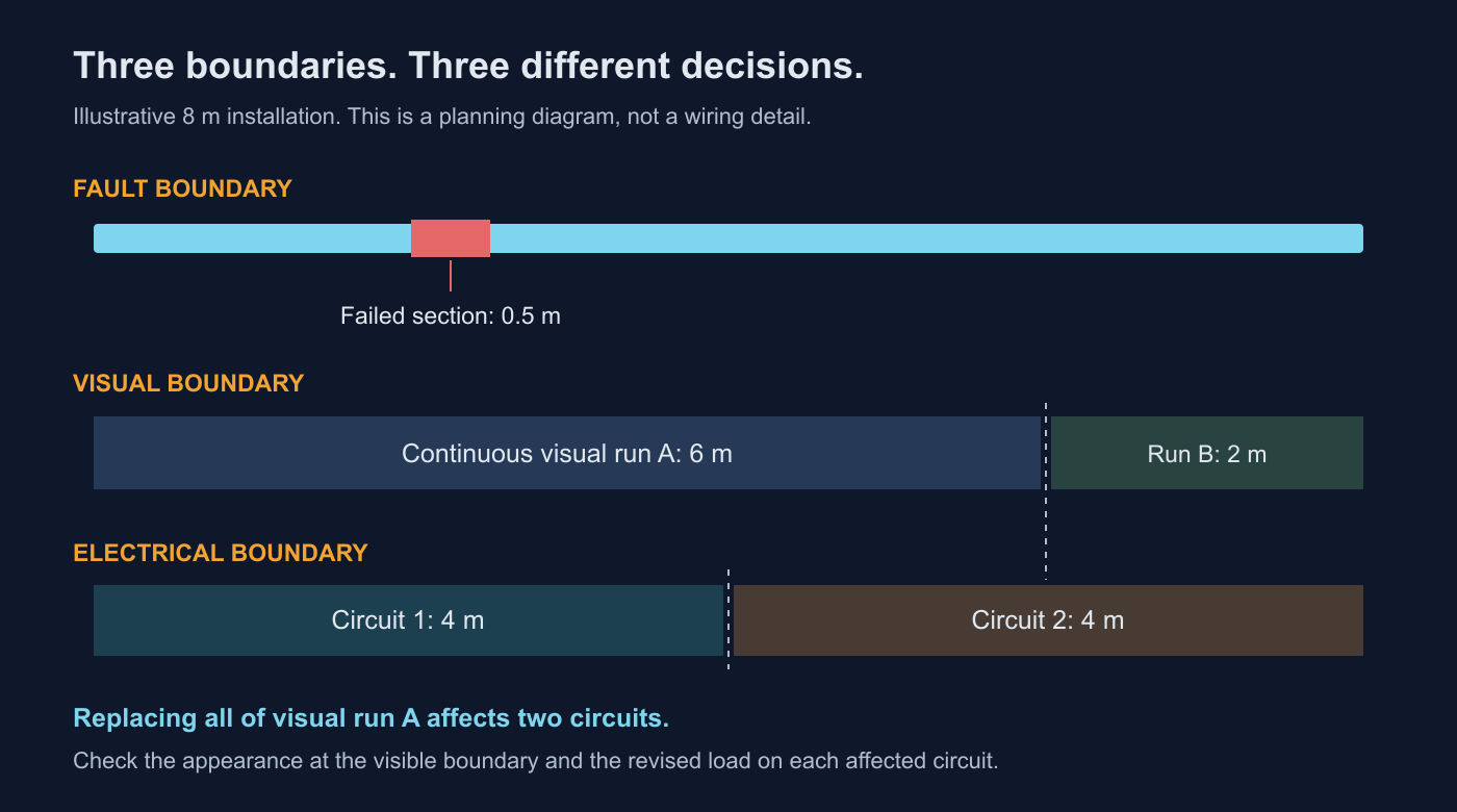
| Scope | Reasonable when | Do not overlook |
|---|---|---|
| Failed section only | The cause is local, a documented compatible replacement exists, and the adjacent visual match is approved. | Extra joints, local heat, termination space, and residual aging. |
| Complete visual run | A continuous cove or shelf makes patching conspicuous, but the retained infrastructure is suitable. | The new total load, feed positions, cover condition, and remaining runs in view. |
| Complete lighting assembly or zone | Records are missing, several components are degraded, or control and mounting compatibility cannot be established. | Expanded electrical design, access, commissioning, and applicable approval requirements. |
Price these options separately. Include access equipment, finish protection, downtime, new joints, and repeat commissioning. Do not assume complete replacement is always cheaper, or that a patch is always economical. A clearly priced visual-match risk is more useful than an unsupported promise of an invisible repair.
8. Retest Dimming Even When the Replacement Uses Less Power
Lower wattage can improve the power budget without preserving the dimming response. MEAN WELL’s application note demonstrates load-dependent dead travel when particular current-amplitude dimming drivers operate resistor-based tape, and explains the different behavior of PWM output.[1] This is a reason to test the exact driver-load combination, not a universal claim that every lower-power replacement will dim badly.
Record the full control chain: wall control or bus, driver, separate controller if present, and tape. Test starting from off at the lowest intended scene, fading down and back up, repeated switching, scene recall, and power restoration. Also check audible noise, visible flicker, delayed starts, and mismatched behavior between old and new runs.
Lutron cautions that traditional incandescent load specifications cannot simply be applied to LED loads on its dimming controls.[3] For phase-cut systems in particular, use the manufacturer’s LED compatibility information and exact model limits. Do not add improvised dummy loads to force operation.
For tunable white, test endpoints and intermediate mixes. For camera-facing spaces, retest the intended camera settings rather than relying only on the naked eye. RH’s dimming-method guide explains the main control choices.
9. Preserve the Approved Assembly and Its Documentation
First ask the original luminaire manufacturer whether the proposed part is an authorized service replacement. A component’s individual certification is not proof that every assembly containing it has been evaluated. UL’s retrofit guidance distinguishes evaluated kits and their installation instructions from arbitrary component combinations.[4] The applicable route depends on the product, modification, and jurisdiction; confirm it with the responsible manufacturer and local authority where required.
Manufacturer-supported replacement paths can be specific. Lutron, for example, publishes a field-replacement program with documentation for covered driver families.[5] That does not authorize unrelated substitutions. Keep model identifiers and written compatibility guidance with the maintenance record.
After the approved repair, run the completed assembly with covers and access panels in their normal positions until temperatures stabilize. Check component temperatures against their documented limits, verify the intended brightness and control scenes, and record any changes to the wiring schedule. A brief open-channel power-on is not the same as acceptance in service.
10. Build a Replacement Record That the Next Technician Can Use
Label the serviced zone and record the installed tape model and revision, batch, voltage, W/m, length, cut increment, driver and controller models, channel allocation, diffuser, and feed locations. Keep photographs of terminations and the approved operating scene. Record which components were retained, why they were accepted, and which fault cause was corrected.
Hold practical spare lengths and relevant accessories under the supplier’s storage conditions. An unused spare can reduce procurement uncertainty, but it will not age optically at the same rate as a working installation. It is a reference and service resource, not a guarantee that a future patch will be invisible.
No product family is a universal drop-in replacement. RH can help compare tape options against the information you provide; final suitability requires the exact system documentation and an installed sample where appearance or control behavior is critical.
Common Replacement Questions
Can I replace SMD tape with COB tape?
Potentially, but not on appearance alone. Match electrical architecture, load, dimensions, cut increment, terminations, and environmental requirements. Then test the output through the retained diffuser. A smooth bare COB line does not guarantee the same finished distribution.
Can I keep the old driver?
Only after its model, condition, operating limits, output mode, and dimming compatibility have been established. A driver that still switches on is not automatically suitable for the new load.
Should I replace an entire room because one segment failed?
Not automatically. Start with the fault cause and an adjacent sample comparison. Expand the scope only when compatibility, visible continuity, component condition, or the economics of repeat access justify it.
Specify the replacement before ordering the roll
Send the strip and driver markings, controller model, installed length, channel dimensions, diffuser photos, and a view of the surviving lighting. Include any limits on shutdown time or access so the proposed scope can be assessed realistically.
Discuss Your LED Strip ReplacementThe best repair is not defined by how closely the new roll resembles the old one. It is defined by a compatible, serviceable assembly that performs acceptably in the real space, with the replacement boundary and remaining risks agreed before installation.
References
- MEAN WELL: How to select a LED driver to DIM LED Strip? Driver output behavior and load-dependent dimming in the specific systems discussed.
- U.S. Department of Energy: LED Basics Color appearance, the limits of CCT, and color shift during service.
- Lutron: Application Note 487, Minimum and Maximum Loads for LED and CFL Lamps/Fixtures Why traditional-load limits should not be assumed to apply to LED control loads.
- UL Solutions: LED Retrofit Luminaire Conversion Kit FAQs Evaluated retrofit kits, component markings, and application-specific installation instructions.
- Lutron: LED Driver Field Replacement An example of a manufacturer-supported replacement program; its scope is not a general authorization for other products.
Request a Project or Trade Quote
Sourcing for an installation project, resale or OEM production? Share your requirements below. You can discuss project samples before committing to a bulk order.
Related Articles

LED Strip Lighting After a Power Outage: Designing a Reliable Restart
Plan LED strip power restoration beyond total watts. Review driver inrush, switching limits, restart scenes, and commissioning before project handover.

Why LED Strip Lights Buzz When Dimmed: A Guide for Quiet Spaces
Diagnose LED strip buzzing without guessing. Review drivers, PWM controls, mounting resonance, and low-level acoustic acceptance for quiet interiors.

LED Strip Lighting for Modular Retail Shelves: Design for Reconfiguration
Specify modular shelf lighting beyond driver wattage. Check shared-feed current, connector durability, cable movement, controls, and approved configurations.