
LED Backlighting for Translucent Stone and Resin Panels: Spacing, Depth, and Uniformity
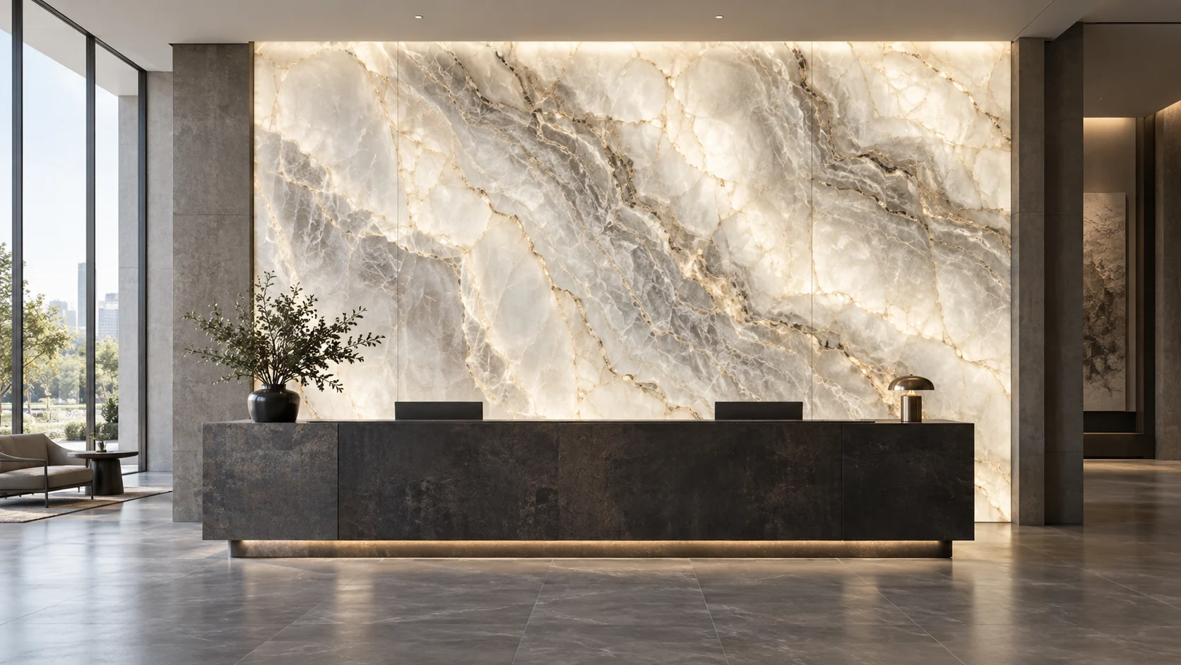
A backlit reception wall looks simple from the front: stone or resin, a frame, and a soft field of light. Behind the finish, however, a linear source must become a two-dimensional luminous surface. That conversion is where expensive projects develop bright stripes, dark borders, visible supports, and color differences between panels.
The common purchasing mistake is to ask only for a brighter or denser LED strip. A smooth COB line can still produce a striped wall when adjacent rows are too far apart. More power makes both the bright and dark areas brighter without necessarily improving their relationship. A successful specification connects the material, optical cavity, row layout, electrical loading, and replacement route.
1. Establish Whether the Panel Can Be Backlit
Begin with a sample of the actual finish, including its specified thickness, backing, adhesive, mesh, printed layer, or protective film. A small unbacked stone offcut can transmit light very differently from the reinforced assembly delivered to site. Do not assume that all stone sold under a similar commercial name has the same translucency.
Inspect the sample with the light off and on. Mark opaque regions, resin-filled features, changes in thickness, and areas where the supporting structure becomes visible. Ask the fabricator which variation belongs to the material and which constitutes a manufacturing defect. This agreement prevents the lighting contractor from being asked to erase natural veining by adding more LEDs.
Engineered resin and acrylic panels also vary. 3form offers different diffusion and translucency treatments for backlit applications.[1] The implication for a project is straightforward: specify the exact material code and finish, not simply “white translucent panel.” Keep an approved physical sample for later comparison.
2. Choose an Optical Architecture Before Buying Strip
There are two main approaches. A direct-lit cavity places distributed LED rows behind the surface. An edge-lit system couples light into an engineered light-guide panel, which distributes and extracts it over an area. Ordinary clear sheet with tape around the perimeter is not equivalent to a designed light guide.
ACRYLITE explains that backlighting can use diffusing sheets to reduce source hotspots, while edge lighting uses a specialized light-guiding material or an extraction pattern.[2] These are different optical systems, with different constraints on depth, edge treatment, maximum dimensions, and joints.
| Architecture | Useful starting condition | Question to resolve in the mockup |
|---|---|---|
| Distributed strip rows | There is room for a mixing cavity and accessible modular rails. | Can the selected row pitch and depth hide both dots and stripes? |
| Engineered light-guide panel | Depth is tightly constrained and the supplier can design the extraction pattern. | How do panel edges, seams, and thermal conditions appear through the actual finish? |
| Dedicated backlighting modules or sheets | A wide area needs a documented two-dimensional source layout. | Does the module’s stated spacing and depth apply to this material stack? |
Choose the architecture that satisfies the assembled result. A strip supplier should be willing to identify when a dedicated area-lighting system is the more suitable option. For linear-source comparisons, see RH’s COB versus SMD guide.
3. Separate LED Pitch From Row Pitch
For a strip with 120 LEDs per meter, nominal LED pitch along the strip is approximately 8.3 mm. If those strips are arranged in rows 100 mm apart, the second spacing is twelve times larger. Selecting more LEDs per meter addresses one direction of the layout; it leaves the 100 mm row spacing unchanged.
Use three variables on the drawing: p, LED pitch along the strip; s, distance between row centerlines; and d, distance from the emitting surface to the first mixing or diffusing plane. Record any additional gap between that diffuser and the decorative face separately. Total wall build-up is not the same as useful optical depth.
The dimensionless ratio s/d is useful for organizing sample trials. Within the same material stack and source distribution, increasing depth or reducing row spacing generally allows more overlap. But no universal ratio guarantees an acceptable wall: beam distribution, reflective surfaces, diffuser behavior, edge conditions, and panel transmission all affect the result.
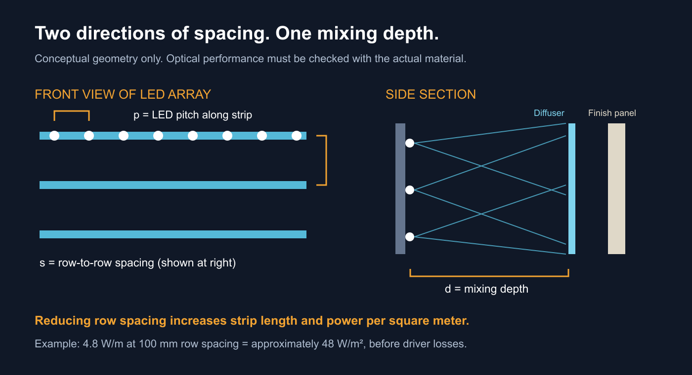
For example, a test with 100 mm row spacing and a 50 mm gap has s/d = 2. Reducing row spacing to 50 mm gives s/d = 1, but approximately doubles strip length per square meter. Increasing the gap to 100 mm also gives s/d = 1, while increasing wall depth. These are alternative trial configurations, not recommended installation limits.
4. Convert Watts per Meter Into Watts per Square Meter
A strip quotation commonly states power per linear meter. The wall experiences the combined load of all rows. For a large, regularly spaced field, approximate strip length per square meter is 1/s, where s is measured in meters. Thus approximate LED power density is q = P/s, where P is strip power in W/m.
| Illustrative strip rating | Row spacing | Approximate strip length per m² | LED load per m² |
|---|---|---|---|
| 4.8 W/m | 100 mm | 10 m | 48 W |
| 4.8 W/m | 50 mm | 20 m | 96 W |
| 9.6 W/m | 100 mm | 10 m | 96 W |
These are arithmetic examples, not RH product claims or thermal ratings. They exclude driver losses and boundary adjustments. Notice that the last two layouts have equal nominal power density but different source spacing. They can produce different uniformity, temperatures, connector counts, and service costs.
A 2 m by 1 m panel with ten 2 m rows contains 20 m of strip. At an illustrative 4.8 W/m, the LED load is 96 W. At 24 V, nominal total current is 4 A. If the selected driver’s instructions and ambient-temperature derating allow an 80% loading target, the arithmetic minimum rating would be 120 W. The actual driver selection must follow its own specifications, minimum-load requirements, and installation conditions. Use the power-supply sizing guide alongside a row-by-row circuit schedule.
5. Treat Diffusion as a Tradeoff You Can Measure
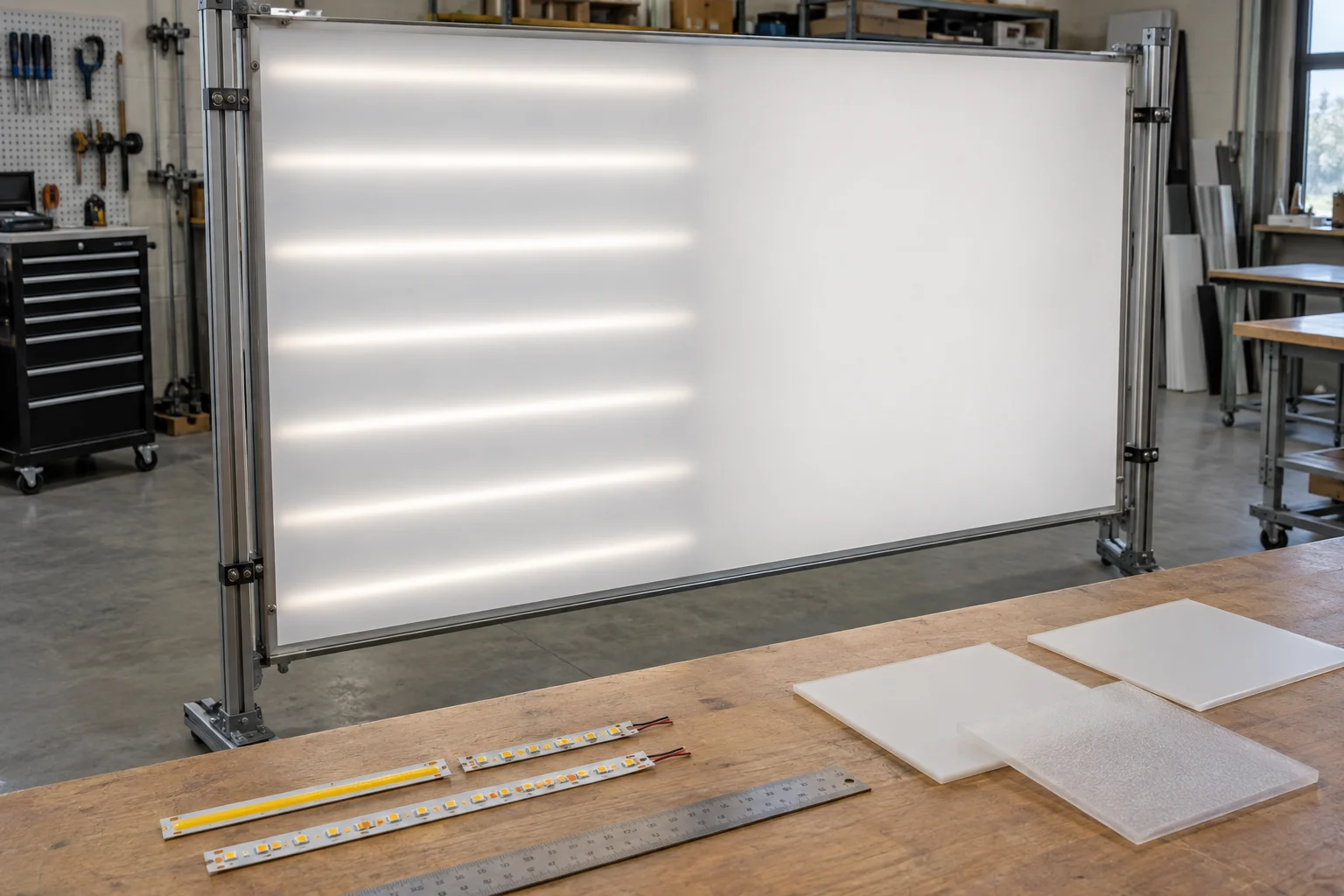
Extra diffusion can reduce the visibility of sources while changing how much light reaches the face. It also changes the angular distribution of that light. Compare both uniformity and brightness when choosing a diffuser; a visually smooth but inefficient stack may require greater electrical loading to reach the desired appearance.
Build trials that change one variable at a time. Keep the source, row layout, material orientation, camera exposure, and operating level fixed when comparing diffusers. Then separately test depth or spacing. Record the final combination rather than naming one sheet as the cause of improvement when several variables changed together.
Use a stable, diffuse, reflective cavity finish approved for the assembly. Dark structural parts and cables can absorb light or cast shadows. A highly reflective cavity is useful only if the selected materials, adhesives, and coatings also tolerate operating temperature and meet the project’s construction requirements.
6. Test Edges, Seams, and Supports Early
An interior point receives contributions from rows on both sides. At a perimeter, neighboring sources are missing, while frames may absorb or block light. Simply repeating the center-field spacing to the edge can leave a dark border. Moving the outer row closer may help, but can instead create a bright rim. Test the complete edge return and masking detail.
Panel joints introduce another pattern. Lumicor’s own backlighting documentation warns that adjacent illuminated panels may show bright or dark lines depending on their edges and the overlay material, and recommends testing diffusion and spacing.[3] A supplier’s uniform single-panel demonstration does not establish that a multi-panel wall will look continuous.
Include a real support rail, bracket, cable crossing, corner, and panel joint in the sample. Ask the structural designer and fabricator to retain required support while coordinating the light path. Do not remove supports to solve a shadow or assume a transparent adhesive will be optically invisible after curing.
7. Separate Material Character From Lighting Defects
Natural stone should not necessarily have uniform face luminance. Its veins and density changes are often the reason it was chosen. A single minimum-to-average ratio across the finished stone can penalize desired texture while missing a broad lighting stripe.
A more useful acceptance process has two stages. First evaluate the light engine with a uniform reference diffuser at the intended location. Use a repeatable measurement grid and record luminance in cd/m² with suitable equipment. Then install the actual decorative panel and compare its appearance with the approved material sample. Evaluate regular stripes, borders, joint halos, and bracket silhouettes separately from natural patterns.
For example, reference-screen readings with Lmin = 320 cd/m² and Lavg = 400 cd/m² give Lmin/Lavg = 0.80. This is only an example of a calculation, not a recommended pass threshold. Agree the limits, sampling positions, viewing distances, ambient light, and treatment of edges before fabrication. A handheld lux reading against the face is not interchangeable with a luminance measurement of the visible surface.
Photographs help document appearance when exposure and white balance are locked, but phone auto-exposure and processing make them unreliable quantitative proof. Keep original images and the measurement sheet alongside the approved sample.
8. Evaluate Color After Light Passes Through the Material
Translucent material filters light. A strip that appears neutral by itself may look amber, greenish, or uneven through the finished panel. Review source options behind the actual material alongside the room’s other lights, both during the day and in the intended evening scene.
CRI and TM-30 describe aspects of source color rendition; they do not directly predict the appearance of every translucent panel. DOE describes TM-30 as a group of related measures and graphics for evaluating light-source color rendition.[4] Use such data to compare sources, then approve the transmitted result physically.
If tunable white is required, test both endpoints and intermediate settings at the intended brightness levels. Multi-channel products may introduce spatial or color differences when the mixing distance is small. See RH’s tunable white specification guide and batch color-consistency guide. Hold approved spare material and light modules where a later mismatch would be costly.
9. Design Power Feeds and Heat Paths Together
A wall can appear uneven because of voltage drop even when the optics are well mixed. Create a circuit schedule listing each row’s length, load, feed cable, driver, dimming channel, and terminal identification. Measure voltage and visible output at the electrically remote points under the actual operating load.
Do not route the combined current of many rows through a connector or PCB track rated for only one row. Parallel feeds can improve distribution, but require appropriately rated conductors, connections, and protection. Keep cables out of the optical path and accessible for inspection. Refer to connection reliability guidance when defining the assembled wiring method.
Operate the closed mockup until temperatures stabilize, including the planned finish, backing, cavity, and surrounding insulation. Record driver case and strip mounting-surface temperatures against component limits. DOE’s reliability work treats LED lighting as a system whose service life depends on components beyond the LED package.[5] A long LED lifetime claim does not establish the life of an enclosed backlighting assembly.
10. Make the Wall Serviceable Before Fixing the Stone
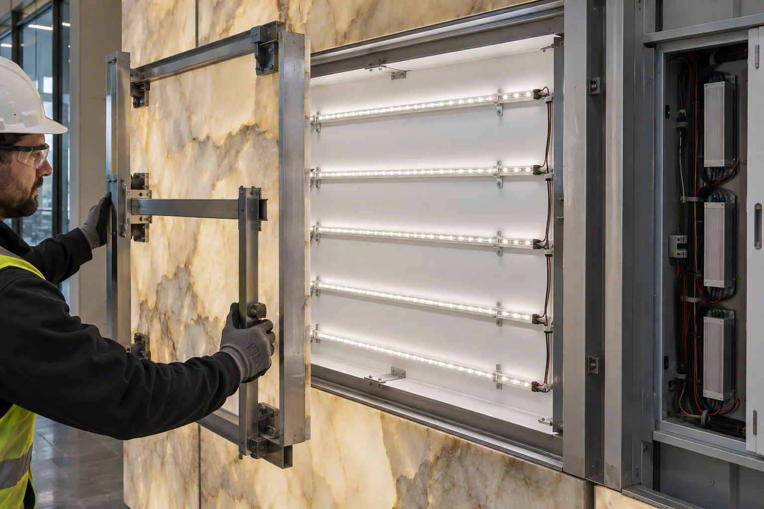
Define which item can be replaced without removing the decorative face: driver, fuse, connector, light rail, or complete optical module. Then simulate the most difficult replacement. A driver that is visible through a small opening may still be impossible to remove with its connectors attached.
The total intervention cost includes access equipment, panel handling, protection of finishes, downtime, reassembly, and color matching. These costs can dominate the price of the failed strip. Prefer a documented module and connector arrangement that permits repeatable positioning after service; shifting one rail can create a new optical pattern.
11. Match Product Choice to the Approved Mockup
Neither product family guarantees a uniformly backlit area. Approve the complete arrangement and record its bill of materials. A replacement diffuser, changed backing, alternative driver, or reduced cavity depth should trigger a review of the relevant sample results.
12. Put Measurable Requirements in the RFQ
| Requirement | Information to provide | Evidence for approval |
|---|---|---|
| Decorative material | Exact sample, thickness, backing, finish, pattern orientation, and panel joints. | Approved illuminated physical sample. |
| Optical geometry | LED pitch, row spacing, source-to-diffuser gap, second gap, edges, and support locations. | Full-size representative section with a seam and perimeter. |
| Appearance | Reference-screen criteria, material variation, brightness scenes, viewing positions, and ambient light. | Luminance grid and controlled visual review. |
| Electrical load | W/m, total strip length, W/m², voltage, feeds, controls, and driver conditions. | Circuit schedule and loaded measurements. |
| Thermal behavior | Closed-cavity build-up, ambient, component limits, and mounting surfaces. | Stabilized mockup temperatures. |
| Service and supply | Removable units, handling access, spare modules, batch traceability, and substitution rules. | Replacement demonstration and approved component list. |
Plan the backlighting with the panel fabricator
Send RH Strip Lighting the material sample, panel dimensions, available depth, support layout, desired color, dimming scenes, and service access. We can help develop strip options and a sample layout for physical evaluation.
Discuss Your Backlit Panel ProjectA strong backlighting specification connects the appearance at the face to the hidden row layout and the cost of maintaining it. Start with the real panel, compare spacing and depth deliberately, calculate the area load, and approve the seams and service route before releasing production.
References
- 3form: Whites, Diffusions and Effects. Material options with different diffusion and translucency characteristics.
- ACRYLITE: Light Transmission and Reflectance. Technical guidance on diffusion and engineered edge-lighting approaches.
- Lumicor: Lumilight Product Overview. Product-specific discussion of panel edges, joints, diffusion, and overlay testing; its dimensions are not universal strip-layout rules.
- U.S. Department of Energy: TM-30 Frequently Asked Questions. Scope and use of light-source color-rendition measures.
- U.S. Department of Energy: LED Systems Reliability Consortium. System-level reliability and lifetime resources.
Request a Project or Trade Quote
Sourcing for an installation project, resale or OEM production? Share your requirements below. You can discuss project samples before committing to a bulk order.
Related Articles
LED Strip Lighting After a Power Outage: Designing a Reliable Restart
Plan LED strip power restoration beyond total watts. Review driver inrush, switching limits, restart scenes, and commissioning before project handover.
Why LED Strip Lights Buzz When Dimmed: A Guide for Quiet Spaces
Diagnose LED strip buzzing without guessing. Review drivers, PWM controls, mounting resonance, and low-level acoustic acceptance for quiet interiors.
LED Strip Lighting for Modular Retail Shelves: Design for Reconfiguration
Specify modular shelf lighting beyond driver wattage. Check shared-feed current, connector durability, cable movement, controls, and approved configurations.