LED Strip Lighting for Cleanrooms and Laboratories: Cleanability, Sealing, and Service Design
LED strip lighting can create a continuous, low-profile light line in cleanrooms, laboratories, pharmaceutical production areas, medical-device facilities, optics rooms, and controlled manufacturing spaces. But a product that is waterproof, bright, and electrically safe is not automatically suitable for a controlled environment.
The real specification problem is the boundary around the light. Every diffuser edge, profile joint, cable penetration, sealant bead, driver location, fastener, and service action can affect cleaning, airflow, particle retention, chemical resistance, temperature, and the validated state of the room. The strip is only one component inside that boundary.

Start With Four Boundaries, Not a Product Code
ISO 14644-1 classifies air cleanliness by the concentration of airborne particles in cleanrooms and clean zones.[1] It does not say that a particular LED strip, profile, or IP rating is automatically acceptable. ISO 14644-4 covers the process of creating a cleanroom through requirements, design, construction, start-up, and verification, while highlighting life-cycle considerations such as maintenance.[2]
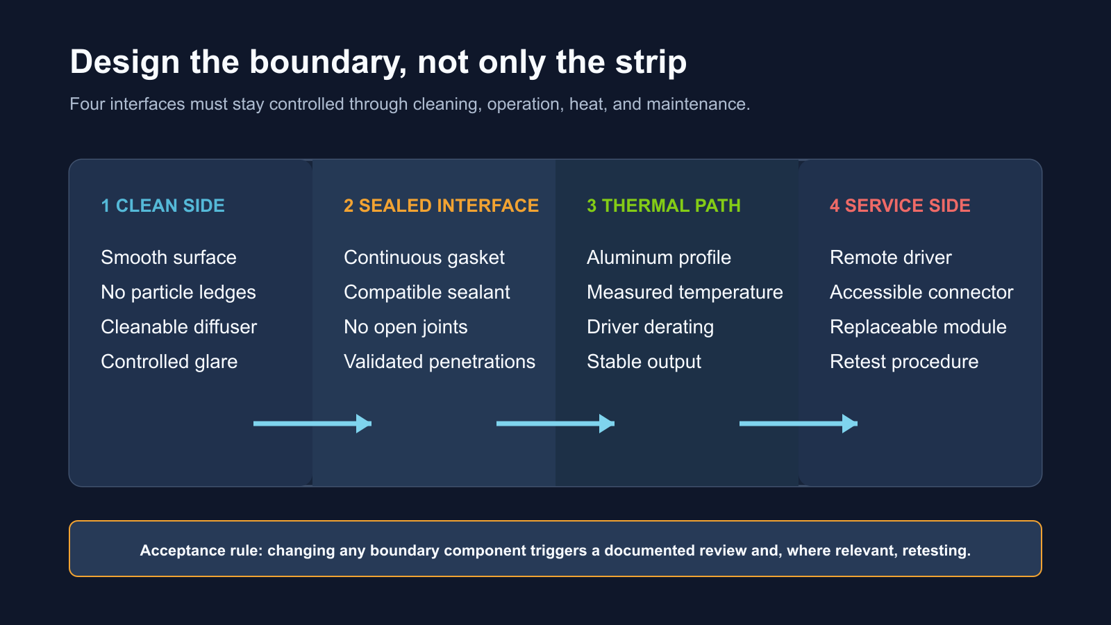
For lighting, those principles become four practical boundaries:
A strong specification names an owner and an acceptance method for each boundary. The cleanroom consultant may own room classification. The architectural system supplier may own the sealed panel interface. The lighting supplier may own photometric and thermal performance. The electrical contractor may own wiring and isolation. The facility quality team may own change control and return-to-service procedures. Leaving any boundary ownerless creates a gap that appears late in validation.
Why “IP65” Is Not a Cleanroom Specification
IEC 60529 defines degrees of protection provided by electrical enclosures against ingress.[5] That makes an IP code useful for a defined enclosure and test condition. It does not, by itself, establish particle emission, resistance to a facility’s disinfectants, cleanability of installed joints, microbiological suitability, compatibility with vaporized agents, or behavior after repeated cleaning cycles.
The distinction matters because buyers often ask for an “IP65 strip” and assume the complete ceiling or wall detail is solved. The rated item may be only the encapsulated strip. The cut end, field connector, diffuser-to-profile joint, cable gland, mounting screw, and transition into the wall can have different protection. A field-cut assembly may no longer represent the tested product configuration.
ISO 14644-14:2026 provides a methodology for assessing equipment suitability with respect to airborne particle concentration, but its official scope explicitly excludes biocontamination, cleanability, decontamination agents, material-selection requirements, and other physical properties.[4] This is useful evidence for a broader lesson: even a cleanroom-equipment assessment has a defined boundary. Procurement should request the evidence required for the project rather than stretching one test beyond its scope.
Design the Clean-Side Surface Before Choosing COB or SMD
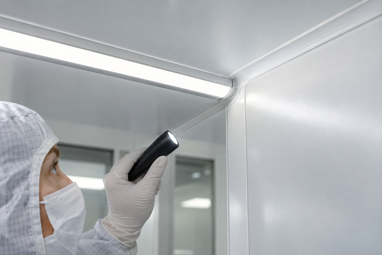
FDA guidance for aseptic processing describes cleanroom floors, walls, and ceilings as smooth, hard surfaces that can be easily cleaned. It also warns against unnecessary fixtures and horizontal ledges that accumulate particles.[3] Although not every laboratory is a sterile-drug facility, the design logic is directly useful: the clean-side detail should avoid traps, rough edges, inaccessible recesses, and geometry that defeats the cleaning procedure.
Start with the installed section. Define whether the diffuser is flush, recessed, or outside the classified envelope. Draw the interface at wall panels, ceiling panels, corners, door frames, glazing, and service penetrations. A continuous luminous line can look simple in elevation while creating dozens of joints in section.
For a flush detail, review:
- whether the exposed surface is smooth and non-shedding
- whether the diffuser can tolerate the approved cleaning method
- whether sealant joints remain continuous around corners and end conditions
- whether clips, screw heads, end caps, and profile lips create particle ledges
- whether the surface can be inspected without removing the optical component
- whether repeated removal changes gasket compression or damages the seal
Select the Strip After the Optical Depth Is Known
COB LED strip is often a useful starting point when the profile is shallow and the diffuser is close to the source, because the dense emitting surface can reduce visible dotting. SMD LED strip can provide a wider range of output, voltage, color, and control configurations when the optical chamber is deeper. LED neon flex may suit a robust self-diffused line outside the critical clean envelope, but its larger section, bend direction, mounting method, and end treatment must be coordinated with cleaning and service requirements.
None of these product families should be selected by appearance alone. Mock up the actual profile depth, diffuser transmission, mounting distance, surface color, viewing angle, and required output. A denser strip cannot compensate for a diffuser that is too close, a highly reflective work surface, or an exposed line that causes discomfort at normal working positions.
For related decisions, see RH’s guides to COB versus SMD selection, aluminum profiles and thermal management, and what IP65, IP67, and IP68 actually describe.
Validate Cleaning-Chemical Compatibility as an Assembly
A material can appear stable after one wipe and still fail after hundreds of cleaning cycles. Diffusers may haze, silicone may swell, labels may release, sealants may crack, coatings may discolor, and adhesives may lose strength. Chemical concentration, contact time, temperature, wiping force, rinse procedure, and frequency all influence the result.
Do not accept a generic statement such as “chemical resistant.” Ask the facility team for the actual approved agents and procedures. Then test representative coupons or a full assembly containing the production diffuser, sealant, gasket, end cap, profile finish, cable jacket, connector, label, and cleaning tool. Include joints and cut edges, because failures often begin at interfaces rather than broad surfaces.
The acceptance record should state:
- chemical name, concentration, preparation, and contact time
- number of simulated cycles and drying conditions
- visual change, haze, cracking, swelling, tackiness, or color shift
- seal continuity and adhesion before and after cycling
- light output and diffuser uniformity after exposure
- whether the test covers routine cleaning, sporicidal cycles, or special decontamination
Where vaporized or aggressive decontamination is used, the project’s validation specialist and material suppliers should define the protocol. A standard waterproof strip should not be assumed compatible without evidence.
Protect Airflow and Pressure Relationships
Cleanrooms are air systems. A bright line placed across a ceiling can obstruct a return path, disturb a unidirectional-flow concept, create a warm plume, or complicate HEPA filter access. A wall-recessed profile can also create leakage paths if penetrations are not coordinated with the panel system and room-pressure strategy.
Coordinate the lighting layout with the cleanroom mechanical designer before fixing positions. The review should include supply and return locations, filter replacement zones, sprinklers, sensors, pressure taps, equipment heat loads, room classification, and airflow visualization requirements. The lighting supplier should not claim that a detail preserves airflow based only on a drawing.
For critical areas, the completed installation may need to be included in facility airflow visualization, room recovery, particle, pressure, or other project-defined verification. The exact test depends on the room and regulatory context. Record the approved fixture position and projection so that a later substitution does not silently change the tested geometry.
Put Heat Where It Can Be Measured and Removed
Encapsulation and sealed cavities can protect an LED assembly from the room while also trapping heat. Higher strip power, narrow aluminum sections, thick diffusers, insulation around the profile, and heavily loaded drivers can raise component temperatures. That can reduce output, accelerate color shift, weaken adhesives, and shorten driver life.
The U.S. Department of Energy’s LED luminaire lifetime guidance emphasizes that system reliability depends on more than LED lumen maintenance; power supplies, optics, solder connections, temperature, and other subsystems can dominate failure behavior.[6] This is especially relevant when a cleanroom detail makes replacement expensive.
Measure the assembled mockup at the worst expected operating condition. Record ambient temperature, strip power per meter, profile temperature, LED-board measurement location where available, driver case temperature, supply loading, stabilized light output, and time to stabilization. Verify both full output and the most common operating scene. A remote driver reduces heat inside the room envelope but does not remove the need to calculate voltage drop and cable size.
Separate the Driver From the Clean Envelope
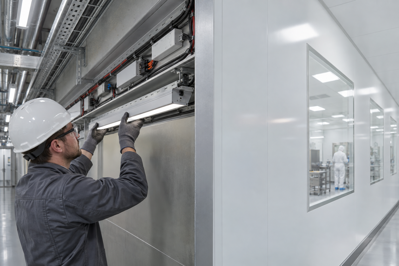
Drivers and control modules are frequent service items. Locating them above a sealed ceiling or behind a permanent wall panel can turn a simple replacement into a cleanroom intervention. The better arrangement is often a remote, labeled, ventilated service location with a defined isolation point and an accessible low-voltage connection to a replaceable light module.
Remote placement introduces its own engineering work. Longer low-voltage cables can produce voltage drop, unequal brightness, or color mismatch between channels. Multiple feeds must be documented. Drivers must be loaded within their approved range and derated for the service-space temperature. Control wiring, emergency functions, and fault behavior should be agreed before installation.
Use RH’s power-supply sizing guide as a starting point, then complete the project calculation using actual run lengths, cable sizes, feed positions, driver data, and measured end-of-run voltage. For controlled scenes, also review LED strip dimming methods.
Control Flicker, Color, and Visual Fatigue
Laboratory work can involve fine inspection, microscopy, transparent vessels, glossy instruments, screens, and long periods of concentration. A clean installation can still be visually poor if the diffuser clips into a bright line, reflects in stainless steel, produces high contrast, or flickers at low dimming levels.
Specify the lighting effect at the work plane and normal eye positions. Check illuminance, uniformity, source luminance, reflections, task shadows, CCT, color rendering, and temporal behavior. If cameras or machine-vision systems operate in the room, test the selected strip-driver-control combination at the actual frame rates, exposure settings, and dimming levels.
Color consistency also matters across long lines and replacement modules. Record the approved CCT, chromaticity tolerance, color-rendering data, batch identification, and operating temperature. RH’s guide to LED binning and MacAdam ellipses explains why nominal CCT alone is insufficient. For temporal issues, see the guide to professional LED-strip flicker.
Certification Must Cover the Right Product and Installation
Electrical safety and cleanroom suitability remain separate questions. UL Solutions identifies standards including UL 1598 for luminaires, UL 8750 for LED equipment used in lighting products, and UL 2108 for low-voltage lighting systems.[7] The applicable route depends on the market, product construction, supply architecture, and how the components are integrated.
Ask for certificates, reports, and markings that identify the exact model and configuration being supplied. A certified driver does not certify a field-built profile assembly. A recognized component is not necessarily a listed complete luminaire. A general family certificate may not cover a customized PCB width, encapsulation, connector, cable, or power level.
The project electrical engineer, cleanroom designer, quality team, and authority having jurisdiction should define the required evidence. The supplier’s job is to make the proposed bill of materials traceable and to disclose substitutions before shipment.
Build a Boundary-Based Mockup
A useful sample is not a one-meter strip glowing on a table. Build a representative section that includes the cleanroom panel, profile, diffuser, gaskets, sealant, end condition, cable entry, driver, connector, mounting hardware, insulation condition, and service access. Include the tightest corner and the most difficult penetration.
- Clean-side review. Inspect smoothness, ledges, exposed hardware, seal continuity, corners, glare, reflections, and accessibility to cleaning tools.
- Particle and airflow review. Use the project-defined assessment for equipment and installed geometry; do not infer room compliance from the LED product alone.
- Chemical-cycle review. Test the complete exposed material stack with the approved cleaning and decontamination procedures.
- Thermal review. Operate the final load until temperatures and light output stabilize under the worst expected ambient condition.
- Electrical review. Verify driver loading, protection, cable size, voltage at both ends, isolation, grounding strategy, and fault behavior.
- Optical review. Measure the work plane and review glare, reflections, color, dimming, camera behavior, and visible uniformity.
- Service simulation. Replace one driver and one light module through the planned access route, then restore seals and settings.
- Return-to-service review. Document cleaning, inspection, change control, retesting, and approval required after maintenance.
Cleanroom LED Lighting Acceptance Schedule
| Field | Record before approval | Acceptance evidence |
|---|---|---|
| Room context | Room use, classification, pressure relationship, process risk, cleaning regime, airflow concept, and applicable standards. | Approved room data sheet and responsibility matrix. |
| Clean-side detail | Profile section, diffuser, exposed edges, joints, corners, fasteners, sealant, gasket, and surface finish. | Full-scale mockup and visual/cleanability review. |
| Material compatibility | Cleaning agents, concentrations, contact times, cycle count, temperature, rinse, and wipe method. | Coupon or assembly test with documented pass/fail criteria. |
| Ingress boundary | Rated enclosure, cut ends, connectors, cable glands, penetrations, field joints, and installation instructions. | Model-specific documentation plus installed-joint inspection. |
| Optical performance | Output, diffuser transmission, illuminance, uniformity, glare, CCT, color data, dimming, and camera requirements. | Photometric data and installed mockup measurements. |
| Thermal performance | Watts per meter, profile, ambient, insulation, driver load, cable route, and operating scene. | Stabilized temperature and output measurements. |
| Electrical system | Voltage, driver, protection, cable size, feed points, control, emergency role, isolation, and certification path. | Approved single-line diagram and commissioning results. |
| Service plan | Replaceable unit, access side, tools, spares, seal restoration, cleaning, change control, and retest trigger. | Timed replacement simulation and return-to-service procedure. |
What to Include in the RFQ
- room type, cleanroom classification, process, and regulatory context
- wall and ceiling panel drawings with every profile, corner, joint, and penetration
- required lighting effect, work-plane target, viewing angles, glare limits, CCT, and color tolerance
- cleaning and decontamination agents with concentration, contact time, and cycle expectations
- airflow concept, pressure boundary, filter/service zones, and restrictions on projections or ledges
- strip type, voltage, watts per meter, run lengths, feed locations, dimming, and controls
- profile, diffuser, gasket, sealant, end cap, connector, cable, and mounting requirements
- ambient range, thermal limits, test method, driver location, and service-space conditions
- required certifications, reports, model traceability, batch control, and substitution rules
- mockup scope, chemical-cycle test, service simulation, commissioning, spares, and retest triggers
Specify the complete cleanroom lighting boundary
Send the room classification, panel section, cleaning protocol, optical target, strip lengths, voltage, driver location, control method, and service plan. RH Strip Lighting can help compare the strip, profile, diffuser, wiring, and sample assembly for project testing.
Request a Cleanroom Lighting RecommendationConclusion
LED strip lighting can support a clean, continuous architectural detail in laboratories and controlled environments, but only when the project specifies more than the strip. The successful unit is the complete boundary: a smooth clean-side surface, a controlled sealed interface, a measured thermal path, and a service route that does not casually compromise the room.
The best procurement question is therefore not “Which IP-rated strip should we buy?” It is “What evidence proves that this installed assembly can be cleaned, operated, maintained, and returned to service under our actual room conditions?” Once that question is answered, product selection becomes more accurate, substitutions become easier to control, and validation risks become visible before construction.
References
- ISO 14644-1:2015, Cleanrooms and associated controlled environments — Classification of air cleanliness by particle concentration.
- ISO 14644-4:2022, Design, construction and start-up of cleanrooms and associated controlled environments.
- U.S. FDA, Sterile Drug Products Produced by Aseptic Processing — Current Good Manufacturing Practice.
- ISO 14644-14:2026, Assessment of suitability for use of equipment by airborne particle concentration.
- IEC 60529, Degrees of protection provided by enclosures (IP Code).
- U.S. Department of Energy, LED Luminaire Lifetime: Recommendations for Testing and Reporting.
- UL Solutions, Lighting Safety Testing and Certification.
Request a Project or Trade Quote
Sourcing for an installation project, resale or OEM production? Share your requirements below. You can discuss project samples before committing to a bulk order.
Related Articles

LED Strip Lighting After a Power Outage: Designing a Reliable Restart
Plan LED strip power restoration beyond total watts. Review driver inrush, switching limits, restart scenes, and commissioning before project handover.

Why LED Strip Lights Buzz When Dimmed: A Guide for Quiet Spaces
Diagnose LED strip buzzing without guessing. Review drivers, PWM controls, mounting resonance, and low-level acoustic acceptance for quiet interiors.
LED Strip Lighting for Modular Retail Shelves: Design for Reconfiguration
Specify modular shelf lighting beyond driver wattage. Check shared-feed current, connector durability, cable movement, controls, and approved configurations.