
LED Strip Lighting for Broadcast Studios and Video Sets: Flicker, Color, and Camera Testing
LED strip lighting can make a broadcast set feel deeper, cleaner, and more expensive on camera. It can outline acoustic panels, separate a presenter from the background, create a controllable practical light, and let one physical set support several programs. But a strip that looks perfectly steady and white in the studio can record as horizontal bands, exposure drift, color mismatch, clipped highlights, or an impossible post-production correction.
The reason is simple: people see a space, but cameras also sample time. The final specification must therefore describe not only brightness, CCT, CRI, and appearance, but the complete relationship among LED waveform, driver, decoder, dim level, frame rate, shutter, sensor readout, lens, camera profile, and control cue.
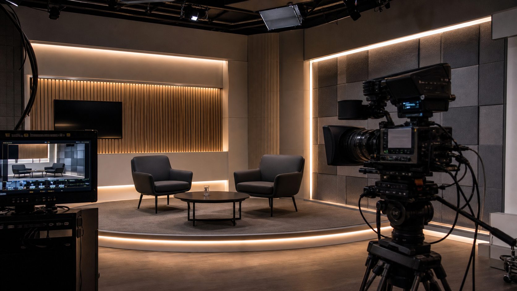
Approve the System in Four Dimensions
Broadcast set lighting fails when one metric is allowed to represent the whole installation. CRI cannot describe temporal behavior. A high PWM frequency cannot guarantee good color. A clean waveform cannot prevent a bright diffuser from clipping in the shot. A beautiful mockup cannot prove that a hidden driver can be replaced between productions.
Each dimension needs its own evidence and pass/fail rule. This prevents a visually smooth COB strip with the wrong driver, or a camera-stable driver connected to a visibly dotted strip, from being approved as a system.
Why the Eye Can Miss Camera Banding
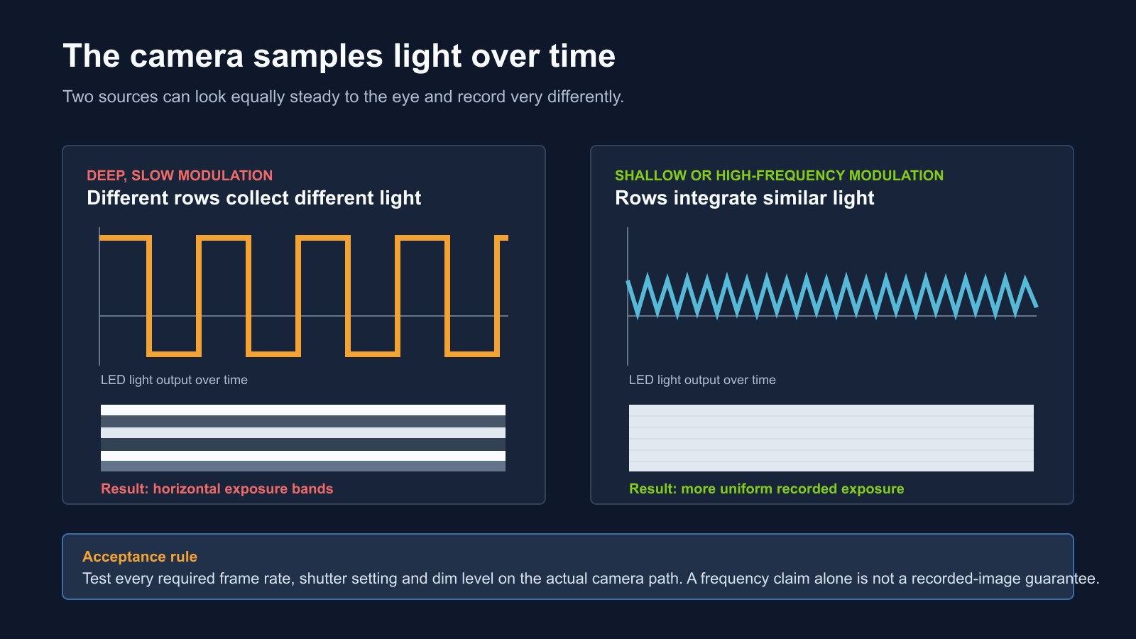
LEDs respond rapidly to changes in current. A driver or decoder can reduce light by lowering current, by switching the LED on and off through pulse-width modulation, or by combining methods. The eye may integrate those variations into apparently steady light. A camera exposes pixels or rows over defined time windows, so it may record different amounts of light at different positions in the frame.
The U.S. Department of Energy describes this rapid variation as temporal light modulation and notes that LED behavior depends on waveform shape, modulation depth, duty cycle, and frequency.[1] These variables matter independently. “PWM at 4 kHz” says nothing about the depth of modulation, behavior at 5% output, interaction with a rolling shutter, or whether another stage in the decoder-driver chain introduces a lower-frequency envelope.
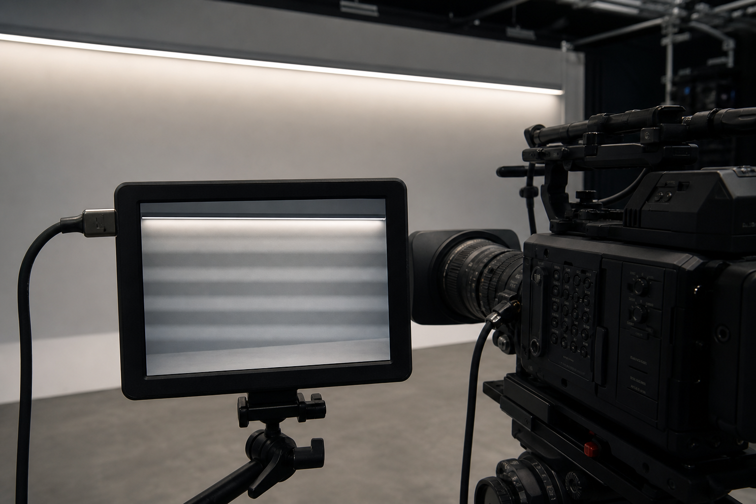
Sony’s camera documentation provides a practical illustration: its variable-shutter function finely adjusts shutter speed to reduce band-like light and dark shading under artificial sources such as LEDs, and Sony advises checking the recorded image because the result depends on the source and shooting condition.[2] Variable shutter is a useful production tool, but a permanent set should not force every camera department to abandon a preferred shutter simply to accommodate decorative strips.
Build a Camera Test Matrix, Not a Single Demo
A supplier video recorded at one frame rate and full brightness is not a broadcast acceptance test. The project should list every mode the studio expects to use. A news set may operate at 25 or 50 fps in one market; a streaming studio may use 29.97 or 59.94; a commercial shoot may use 23.976 or 24; slow-motion inserts may use much higher frame rates. Shutter angle or shutter speed can also change for motion rendering, display synchronization, or special effects.
Test at least these variables:
- all required frame rates and sensor scan modes
- the normal shutter plus the fastest and slowest planned alternatives
- every camera family and output path used for acceptance
- 100%, 50%, 20%, 10%, 5%, and minimum usable dim levels
- static framing, pans, tilts, focus pulls, and moving reflective objects
- single-strip operation and the largest simultaneous control cue
- cold start, thermal stabilization, standby, and power recovery
Record the actual camera output, not only a phone screen pointed at a monitor. Review waveforms or false color for exposure changes, inspect shadows and midtones for bands, and compare clips at normal playback and frame-by-frame. Dark wall finishes often reveal subtle modulation more clearly after gain, gamma, or log-to-display transforms.
Do Not Specify PWM Frequency Alone
A higher modulation frequency generally gives the camera more cycles to integrate during an exposure, but no single number guarantees every production mode. The DOE’s flicker research notes that avoiding deep PWM oscillation or using very high frequency—greater than 12,000 Hz and possibly higher—can reduce complications, while also emphasizing that temporal behavior depends on the waveform.[1]
Ask for instrument data at the system output:
- light-output waveform at full, mid, low, and minimum levels
- dominant and secondary modulation frequencies
- modulation depth and duty cycle at each level
- measurement setup, sensor bandwidth, distance, and sample rate
- driver, decoder, controller, firmware, load, strip length, and voltage used
- behavior during fades, color transitions, cue changes, and power recovery
Human-oriented metrics remain useful for occupant comfort, but they are not substitutes for camera tests. IEEE 1789 addresses modulation of high-brightness LEDs and practices intended to mitigate health risks to viewers.[3] Broadcast capture adds another observer—the camera—with exposure windows and sensor readout behavior that human-vision recommendations were not designed to certify.
Choose the Dimming Architecture Before the Strip
The control interface and the output method are not the same thing. DMX, DALI, 0–10 V, phase control, and a local dimmer describe how a command reaches a device. The decoder and driver decide how current reaches the LEDs. A smooth 16-bit console fade can still end in low-frequency, deep PWM at the strip.
For a set-integrated practical, document the entire chain:
Console or building control → network gateway → decoder → driver or power stage → cable → LED strip.
Test the selected hardware together at the real load. Some products change dimming method or modulation behavior near the bottom of the curve. Minimum-load behavior, decoder channel loading, shared power supplies, refresh rate, and firmware can all affect the recorded result. A substitute driver should trigger a new camera test rather than being accepted as electrically equivalent.
For more control-system context, see RH’s guides to LED strip dimming methods and DMX512 versus DALI.
CRI Is Not a Camera-Matching Metric
CRI can be part of a product specification, but it does not simulate a camera and display chain. The European Broadcasting Union’s Tech 3355 states that TLCI was designed to assess lighting for television production and improve on CRI for that application. TLCI uses a model of a television camera and display to evaluate the colorimetric result.[4]
Request a spectral power distribution and TLCI data for camera-facing practicals. Also use TM-30 where broader fidelity, gamut, and hue-shift information supports material and skin-tone decisions. The U.S. Department of Energy describes ANSI/IES TM-30-24 as a system of related measures and graphics that communicates more than one color-rendering number.[5]
Neither TLCI nor TM-30 should be reduced to a badge. Compare proposed strips with the studio key and fill sources, the actual camera profiles, and representative skin tones, wardrobe, graphics, wood, paint, and acoustic fabric. Two nominal 3200K sources can have different spectra and require different camera corrections.
Control Color Through the Full Dimming Range
A practical strip may be calibrated at full output and then operated at 12% for most programs. Measure CCT, Duv, spectral shape, and camera appearance at the levels used on air. Drivers, multi-channel mixing, and thermal changes can shift the result as output changes.
For tunable white, specify channel behavior and crossfade quality, not only the two endpoint CCTs. Confirm whether intermediate whites remain near the intended chromaticity path, whether both channels share compatible temporal behavior, and whether a cue is repeatable after restart. For RGBW or RGB+CCT effects, camera-test saturated colors for clipping, uneven diffusion, color separation, and unexpected interactions with compression or chroma subsampling.
RH’s tunable white specification guide and LED binning and color-consistency guide provide related selection context.
Design the Luminous Line for the Lens
A practical that occupies only a small area of the frame can still exceed the camera’s highlight range. A diffuser that looks softly white in person may clip to a featureless line, flare the lens, reflect in a glossy desk, or reveal brightness variation after exposure is set for a presenter’s face.
Review the profile from every planned focal length and camera position. A deeper channel, wider diffuser, larger luminous surface, lower output, or more indirect geometry may improve the image more than a higher LED density alone. Test focus pulls: a smooth line in focus can become distracting bokeh when defocused, especially if spacing or diffuser nonuniformity remains.
COB LED strip is often a strong starting point for shallow, close-view practicals because its high density can create a smoother line. SMD LED strip offers broad output, voltage, color, and control options for deeper profiles and indirect set lighting. The camera result still depends on the selected driver, profile, diffuser, exposure, and viewing geometry.
Also review RH’s articles on COB versus SMD selection, aluminum profiles and thermal management, and glare control.
Keep Power Distribution Out of the Shot and Inside the Specification
Long scenic runs can lose voltage along the cable and PCB. The result may be a visible exposure or color gradient that is subtle to the eye but obvious after camera shading or color grading. Calculate load and voltage drop, define feed points, and measure both ends of the completed run at the lowest and highest operating levels.
Use a common grounding and power strategy appropriate to the control system. Separate sensitive signal routing from power where required. Check whether several decoders or drivers sharing a supply create synchronized or beating modulation patterns. Test the largest cue transition, not only one isolated five-meter sample.
Document normal operation and fault states: loss of network control, decoder restart, power-supply replacement, emergency shutdown, and restoration after an outage. A practical that returns at 100% after a power cycle can overexpose the opening shot even if it is otherwise reliable.
Make the Scenic Lighting Replaceable
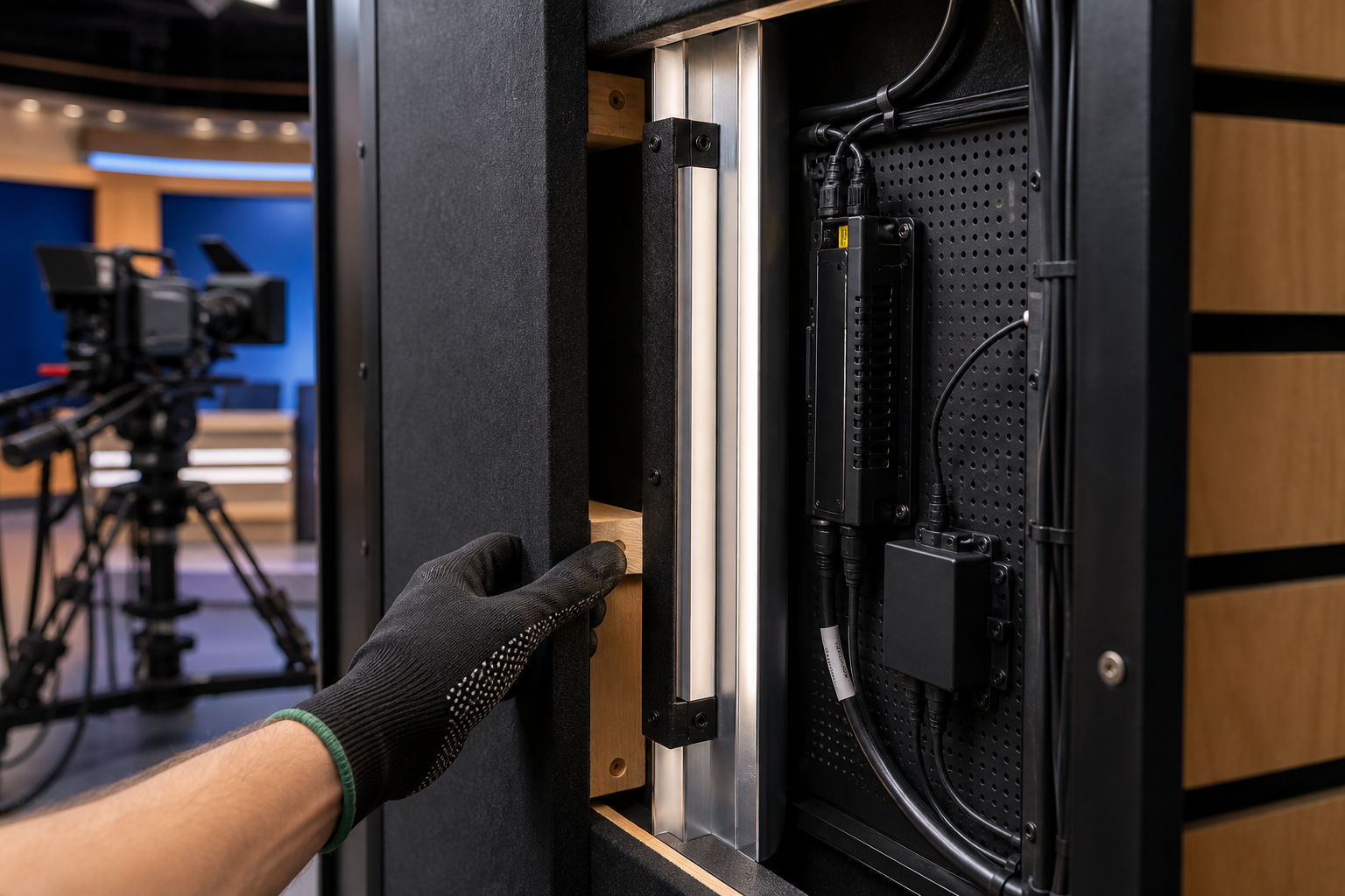
Broadcast sets often run on fixed schedules with little repair time between programs. Drivers and decoders should be ventilated, labeled, and accessible. Profiles should use mechanical retention where possible. Connectors need strain relief and enough service loop to remove a module without pulling a solder joint.
Define replaceable units before fabrication: complete profile modules, cut strip lengths, drivers, decoders, diffusers, cables, and programmed control addresses. Hold color-matched spares for camera-facing runs. A visually similar replacement from a later production batch should be camera-tested before it is mixed into the same shot.
Use an Eight-State Camera Mockup
- Spatial review. Check dots, diffusion, clipping, flare, reflections, exposure ratios, and defocused appearance from every camera position.
- Frame-rate review. Record every required frame rate and sensor mode using the intended production cameras.
- Shutter review. Test the normal shutter plus the full project-approved range, including any variable-shutter setting used in production.
- Dimming review. Record full, mid, low, minimum, fades, blackouts, color transitions, and the largest simultaneous cue.
- Spectral review. Compare skin, wardrobe, graphics, scenic finishes, and other studio sources using the target camera profiles.
- Thermal review. Operate the final load until strip, profile, driver, decoder, and enclosure temperatures stabilize.
- Power-state review. Test control loss, restart, standby, outage recovery, and the default output state of every device.
- Service review. Replace one profile, driver, and decoder through the planned access route, then confirm cue addressing and camera match.
Broadcast LED Strip Acceptance Schedule
| Field | Record before approval | Acceptance evidence |
|---|---|---|
| Camera path | Camera model, sensor mode, frame rate, shutter, codec or output, profile and monitoring transform. | Original recorded clips and test report. |
| Temporal output | Waveform, frequency components, modulation depth, duty cycle and behavior by dim level. | Instrument plots plus camera matrix result. |
| Spectral output | SPD, CCT, Duv, CRI, TLCI, TM-30 and tolerances at operating levels. | Laboratory data and camera comparison. |
| Optical detail | Strip type, density, profile, diffuser, shielding, setback, output and camera viewing angles. | Full-scale scenic mockup. |
| Dimming chain | Protocol, gateway, decoder, driver, firmware, curve, resolution, minimum level and fade behavior. | Approved hardware schedule and cue test. |
| Power system | Voltage, watts per meter, run length, feed points, cable size, supply loading and grounding strategy. | Calculations and end-of-run measurements. |
| Thermal result | Ambient, profile, strip, driver and decoder temperatures under the final cue. | Stabilized mockup measurements. |
| Service plan | Access panels, replaceable module, connectors, addressing, spares and retest procedure. | Timed service simulation. |
What to Include in the RFQ
- set drawings, reveal dimensions, materials, diffuser depth, and camera sightlines
- camera models, frame rates, shutter ranges, sensor modes, and slow-motion requirements
- required CCT, color mode, TLCI, TM-30, CRI, Duv, and batch tolerance
- visible-line, indirect-light, wall-wash, or scenic-outline function for each run
- normal output, minimum output, dimming curve, fade times, and control protocol
- run lengths, feed locations, supply loading, cable distances, and service zones
- required waveform and modulation reporting at multiple dim levels
- mockup, recorded-camera test, thermal test, spare parts, and substitution rules
Specify the recorded result, not only the LED strip
Send the set drawing, camera test matrix, visible-light effect, CCT and color requirements, control protocol, dim levels, run lengths, power locations, and service plan. RH Strip Lighting can help configure the strip, profile, driver, decoder, and sample assembly for camera testing.
Request a Broadcast Set RecommendationReferences
- U.S. Department of Energy, Flicker Research. Overview of temporal light modulation, waveform variables, and high-frequency or non-PWM mitigation approaches.
- Sony ILCE-7M4 Help Guide, Anti-flicker Set. Camera-manufacturer guidance on variable shutter and band-like shading under LED lighting.
- IEEE 1789-2015, Recommended Practices for Modulating Current in High-Brightness LEDs. Standard addressing LED current modulation and viewer health risks.
- European Broadcasting Union Tech 3355, Method for the Assessment of the Colorimetric Properties of Luminaires. TLCI and TLMF methodology for television lighting.
- U.S. Department of Energy, TM-30 Frequently Asked Questions. Guidance on the ANSI/IES TM-30 color-rendition system.
Request a Project or Trade Quote
Sourcing for an installation project, resale or OEM production? Share your requirements below. You can discuss project samples before committing to a bulk order.
Related Articles
LED Strip Lighting After a Power Outage: Designing a Reliable Restart
Plan LED strip power restoration beyond total watts. Review driver inrush, switching limits, restart scenes, and commissioning before project handover.
Why LED Strip Lights Buzz When Dimmed: A Guide for Quiet Spaces
Diagnose LED strip buzzing without guessing. Review drivers, PWM controls, mounting resonance, and low-level acoustic acceptance for quiet interiors.
LED Strip Lighting for Modular Retail Shelves: Design for Reconfiguration
Specify modular shelf lighting beyond driver wattage. Check shared-feed current, connector durability, cable movement, controls, and approved configurations.