
Why LED Strip Lights Buzz When Dimmed: A Guide for Quiet Spaces
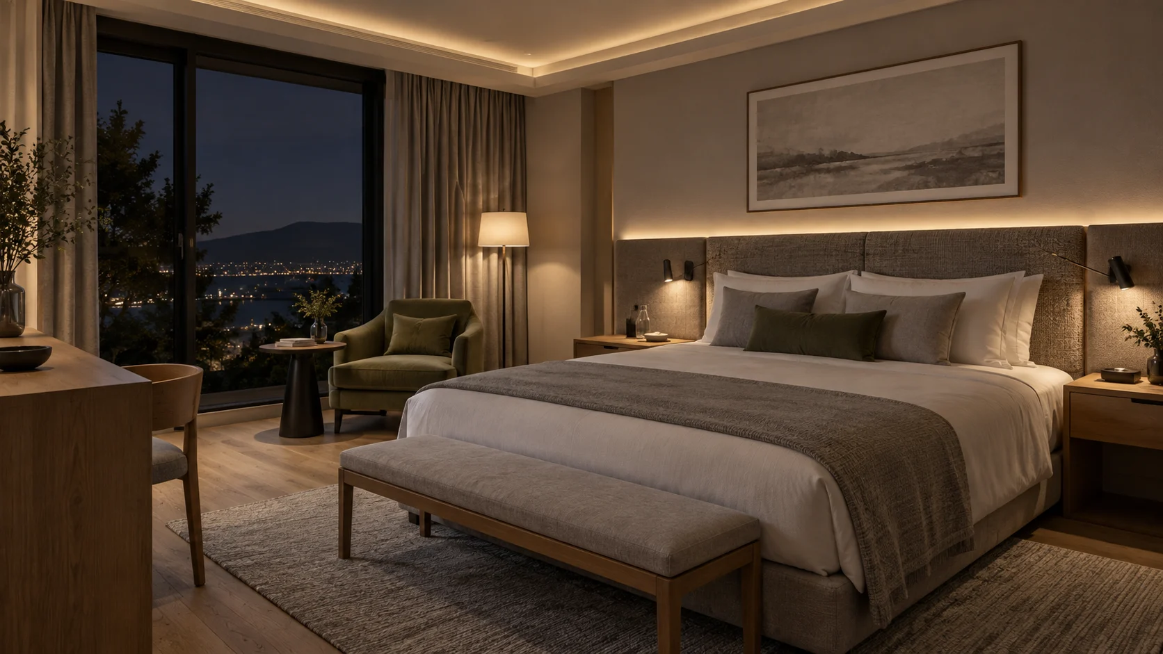
The cove lighting looks smooth. The bedside scene dims low enough. Then the room becomes quiet, and a thin buzz becomes the most noticeable part of the installation. Replacing the LED tape may not solve it, because the sound can originate in the power supply or controller, or be made more audible by the way equipment is mounted.
For hotel bedrooms, reading rooms, private cinemas, and recording spaces, acoustic performance deserves a separate acceptance check. A system that looks right at full output can sound wrong at the exact dimming level the occupant uses most.
This guide is for buyers, lighting designers, and project teams working with low-voltage LED strip systems. It covers selection and non-invasive observations, not live electrical repair. If a noise appears suddenly with burning smells, discoloration, repeated tripping, or abnormal operation, stop using the affected circuit and arrange qualified inspection. Do not assume every sound is harmless coil whine.
1. Identify What Is Actually Making the Sound
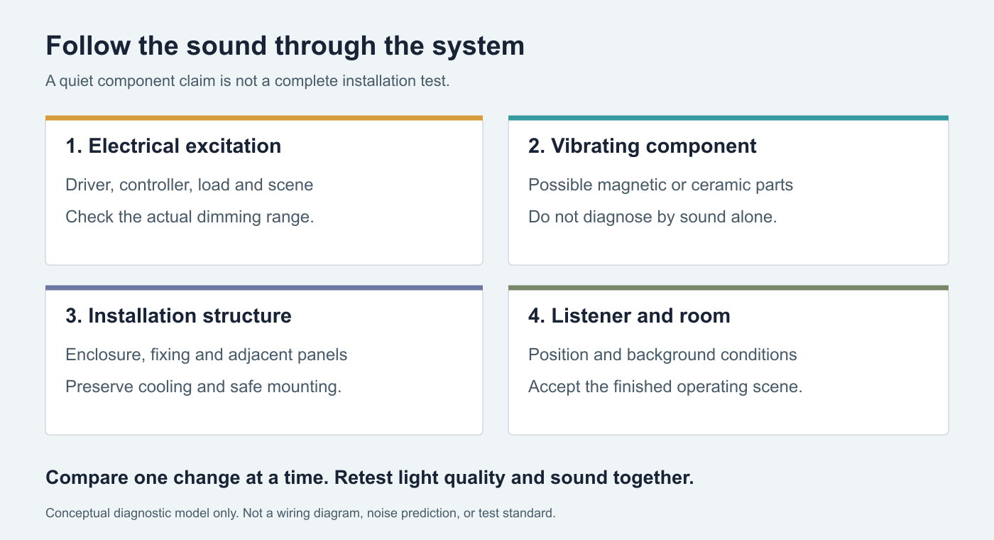
People often say that the strip is buzzing because the sound starts when the strip lights up. That identifies a relationship, not the source. The relevant system may contain an AC dimmer, a power supply, a separate low-voltage controller, and several light modules.
Murata explains how voltage-driven deformation of certain ceramic capacitors can transfer vibration into a circuit board and become audible.[1] Texas Instruments also identifies inductors and ceramic capacitors as possible acoustic sources in a PWM-dimmed LED-driver application.[2] These are possible mechanisms, not a remote diagnosis of a particular installation.
| Where the sound seems strongest | What to investigate | What not to conclude yet |
|---|---|---|
| At the power-supply enclosure | Exact driver model, actual load, and interaction with the dimming arrangement. | That a higher wattage replacement will necessarily be quieter. |
| At a low-voltage controller | Output mode, permitted frequency settings, and connected channel loads. | That changing the LED brand alone will solve it. |
| At a wall dimmer | Compatibility with the specific downstream driver and load. | That every driver marked dimmable accepts that dimmer. |
| Across a cabinet or headboard | Mounting, panel resonance, and the original equipment source. | That the loudest surface contains the faulty component. |
| At powered speakers rather than the fixture | The audio system and possible interference path. | That mechanical acoustic noise and audio interference are the same fault. |
With equipment closed and safely accessible, note the apparent location from outside. Never insert objects through vents, press on live components, or remove covers to find a vibrating part. A technician may need further measurements to distinguish electrical excitation from mechanical transmission.
2. Separate the Control Command From the Output Waveform
A dimming interface tells equipment what light level to produce. It does not, by itself, tell you exactly how the LED current is generated. A digital or 0-10V command may be translated internally into different output behaviors depending on the driver. Likewise, the switching frequency of a power converter is not necessarily the same as the dimming frequency delivered to the strip.
Start by drawing the installed chain. Is there a phase-cut dimmer before a compatible driver? Does a fixed-voltage supply feed a separate PWM controller? Does one integrated device provide both power and dimming? Do not describe all three arrangements simply as a dimmable power supply.
Request model-specific compatibility information and the permitted load range for that architecture. RH’s LED strip dimming-method guide covers the available control approaches. Acoustic acceptance adds a separate question: does the chosen combination remain acceptable throughout its intended operating range?
3. Why Raising PWM Frequency Is Not a Universal Fix
A frequency change can help in a suitable design, but it is not an unconditional prescription. TI’s TPS61181A data sheet discusses audible capacitor noise during PWM dimming and the trade-off between higher dimming frequency and low-duty-cycle performance.[3] That document concerns a particular display-driver IC; its component values and suggested frequencies are not settings to copy into an architectural strip system.
Illustrative timing example: at a 1 kHz PWM frequency, one period lasts 1,000 microseconds. A 1% duty cycle gives a nominal 10-microsecond on-time. At 20 kHz, the period is 50 microseconds and the same duty cycle gives only 0.5 microseconds. These are calculated timing values, not RH product specifications or recommended settings.
The shorter pulse must still be handled by the actual control hardware. Ask the supplier to confirm its supported range and test the resulting low-end dimming behavior. Do not equate a nominal 1% duty cycle with 1% perceived brightness, and do not use 20 kHz as a universal guarantee of inaudibility.
If the product has an approved frequency adjustment, change it only within the manufacturer’s instructions and then recheck the complete system. Quietness, smooth fades, minimum stable output, color behavior, and any camera requirements need to pass together. For camera-facing installations, see the separate broadcast-studio lighting guide; no visible flicker is not proof of acoustic silence.
4. Test the Load Range the Room Will Actually Use
A bench test with a short strip sample does not reproduce the electrical conditions of a full cove. Equally, testing every channel at maximum does not represent a night scene with only one small zone active. Write down the intended combinations before choosing a supply and controller.
For a tunable-white system, include warm-end, cool-end, and mixed settings at the low levels the project needs. For RGBW, include the actual white and color scenes rather than assuming one channel is representative. The relationship between a user-interface percentage and channel loading depends on the product and control mapping.
Do not keep increasing supply capacity as a trial-and-error noise treatment. Headroom is necessary where the product and installation require it, but excess nameplate wattage is not an acoustic rating. Compare suitable models under the intended conditions. Use the power-supply sizing guide for the load budget, then verify noise separately.
5. Review the Mounting Without Compromising Cooling
A small vibration can become more noticeable when equipment excites a large lightweight panel. A supply placed against the back of a hollow headboard may sound different from the same unit in another approved mounting arrangement. Treat the mockup’s cabinet, backplate, and cover position as part of the test, not incidental furniture.
Location also changes the listening relationship. Equipment directly behind a pillow is a different acoustic proposition from equipment in a service area. But relocation is an engineering change: cable length, voltage drop, access, thermal conditions, and applicable installation requirements all need review.
Do not wrap a power supply in foam, block its vents, leave it loose, or modify its internal parts to make it quieter. MEAN WELL’s LED power-supply instructions require suitable ventilation, model-specific mounting and derating checks, and qualified attention to faults.[4] The selected product’s instructions govern; a generic photo or enclosure size does not establish acceptable cooling.
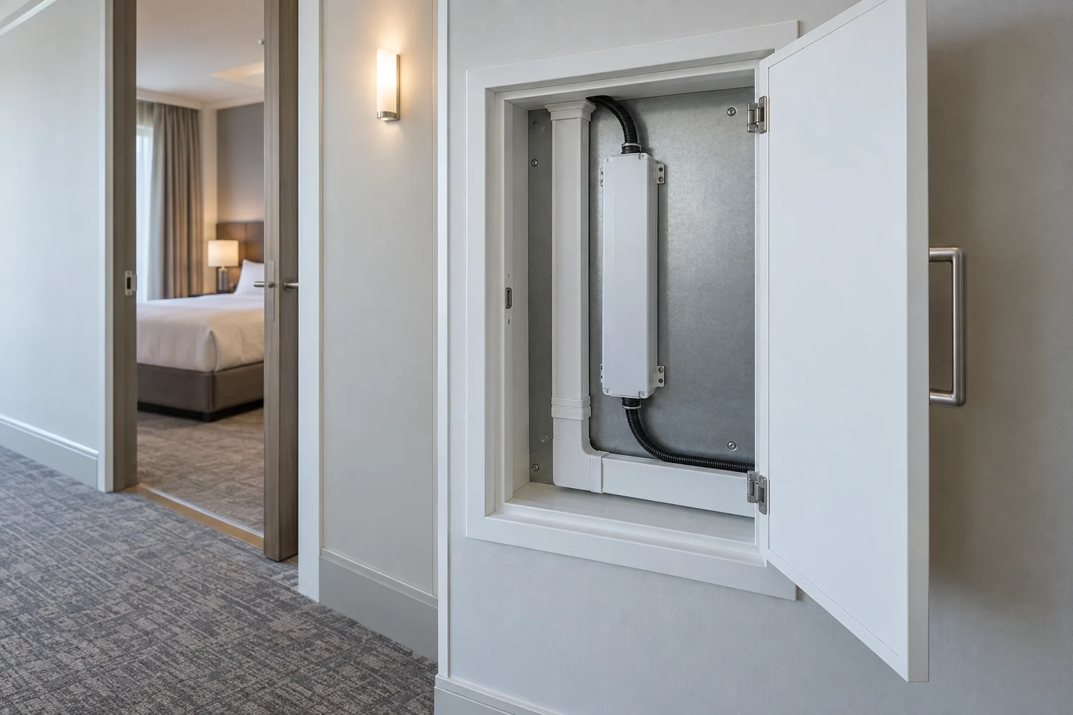
Any isolation mount or alternative fixing should be manufacturer-approved and preserve secure support, required grounding arrangements, and heat transfer. Do not loosen equipment as a listening experiment. For renovation planning, coordinate this review with the hotel-room LED lighting checklist before joinery is closed.
6. Use a Controlled Comparison, Not a Pile of Replacements
Start with a repeatable observation: which zone, which scene, what apparent source, and what room condition? Record the equipment identifiers and settings. Then let the responsible supplier or qualified technician propose a compatible substitution or permitted setting change. Change one variable at a time and retain the result.
A quieter result after replacing a controller is useful evidence about that combination, but it does not prove that every controller from the original family is defective. Conversely, two units showing the same behavior can indicate a design interaction rather than two unrelated failures. Keep diagnosis narrower than the evidence.
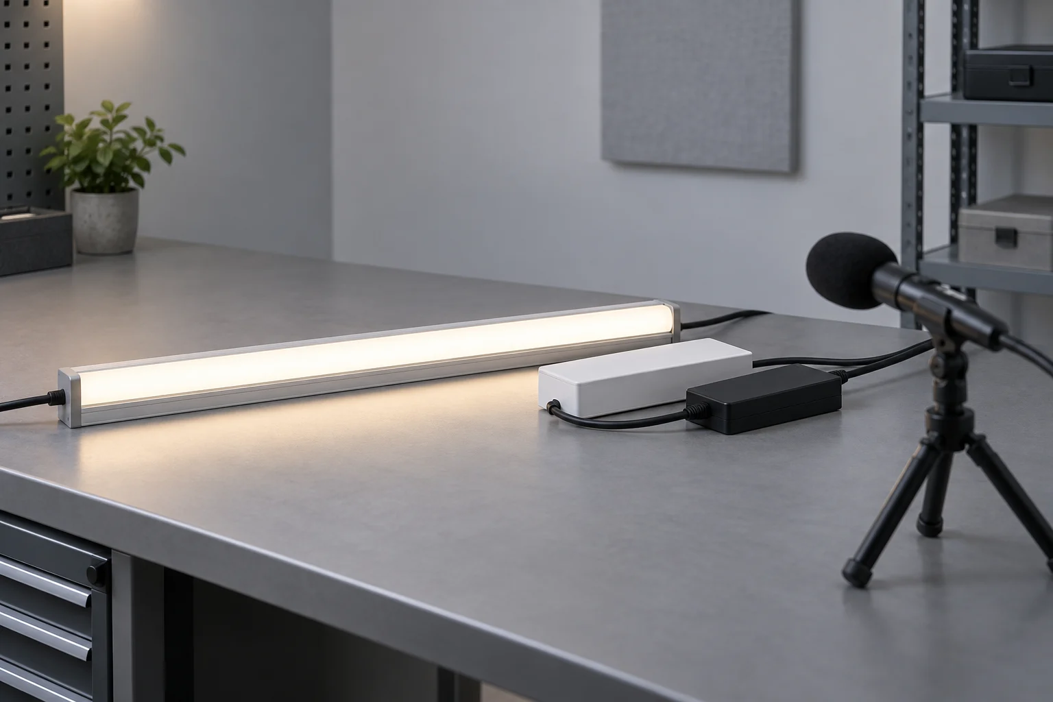
Record sound with the lights off and on under otherwise comparable conditions. A phone recording can help reproduce the symptom and communicate its timing, but do not treat an unverified phone app as a calibrated low-noise acceptance instrument. Background noise, microphone response, recording processing, and position can affect the comparison.
For formal investigation, agree suitable instrumentation and acoustic conditions with the responsible specialist. Murata’s published evaluation approach combines sound-pressure measurements with frequency analysis and electrical investigation to identify a component-level mechanism.[5] That supports an important boundary: hearing or measuring a tone alone does not establish which internal part caused it. Internal electrical investigation belongs to qualified personnel.
7. Write an Acoustic Acceptance Schedule Before Ordering
Replace a vague instruction such as silent dimming with a reviewable schedule. The following is a project checklist, not a published test standard or a universal noise limit. Agree any numerical sound criteria, measurement method, and background-noise requirements with the client and acoustic specialist before testing.
| Test condition | What to record | Why it belongs in acceptance |
|---|---|---|
| Full output and common scenes | Command level, active zones, channel mix, and observed sound. | Establishes the operating baseline rather than just checking that lights turn on. |
| Lowest required stable setting | Actual setting, light stability, and sound at the agreed listener position. | This may be the most important scene in a bedroom. |
| Slow fade in both directions | Any narrow range with a tone, chatter, dropout, or sudden transition. | A few fixed checkpoints can miss a problematic region. |
| Smallest and largest permitted active loads | Connected lengths, enabled channels, and component models. | One load configuration does not represent the whole project. |
| After startup and sustained operation | Elapsed operation, ambient conditions, and any change in behavior. | The accepted condition should represent normal use, not only a brief demonstration. |
| Final installation, covers closed | Mounting, equipment location, room state, and agreed listening positions. | The bench and finished room need not sound the same. |
| Power restoration and recalled scenes | Returned light level, control state, and sound. | Confirms that acceptance survives normal operating transitions. |
Use the quietest normal room condition the project is intended to serve. Record whether HVAC, ventilation, and other equipment are operating; never disable required safety systems for a listening test. A noisy daytime site visit should not be the only basis for accepting bedside lighting.
Do not accept a noise remedy solely because the tone disappears. It must also preserve the required lighting behavior and safe installation. A minimum-level trim that removes buzzing but makes the night scene too bright is a changed specification, not a complete solution.
8. Choose Light Quality and Acoustic Performance Separately
COB and SMD describe light-source construction, not a whole-system sound rating. A continuous-looking COB line can still be connected to noisy power equipment. An SMD installation can be quiet when its complete power and control combination meets the project requirements.
Choose the optical assembly for source visibility, output, color quality, and thermal needs. Then approve acoustic performance with the selected electrical equipment. For practical optical differences, see COB versus SMD for commercial installations. Where variable white is required, include the channel combinations described in the tunable-white specification guide.
Specify the quiet scene before the bulk order
Send RH Strip Lighting the strip lengths, intended light levels, control architecture, equipment locations, and room use. Request model-specific compatibility information and a representative sample combination. Confirm acoustic performance through the agreed mockup; do not assume an untested configuration has a silence guarantee.
Discuss a Quiet-Space Lighting ProjectThe useful question is not simply whether an LED strip can dim. It is whether the installed combination can produce the required light, at the required low level, without an unacceptable sound at the occupant’s position. Test that condition before repeating the same detail across many rooms.
References
- Murata: Why does acoustic noise occur in ceramic capacitors? Component vibration and transfer to the circuit board; not a diagnosis or safety clearance for an installed lighting system.
- Texas Instruments: TPS92692 audible noise in external PWM mode. Manufacturer engineering discussion of possible inductor and capacitor sources. Circuit modifications discussed there are not field-repair instructions in this guide.
- Texas Instruments: TPS61181A data sheet, sections 9.2.2.2 and 9.2.2.3. A device-specific example of audible noise and PWM dimming trade-offs, not an architectural-driver recommendation.
- MEAN WELL: LED Power Supply Installation Manual. Ventilation, mounting, derating, and qualified-service precautions. Follow the instructions applicable to the selected model.
- Murata: MLCC solutions for suppressing acoustic noise in laptop battery lines. Section 5 explains sound and electrical measurements for component diagnosis; its laboratory method is not a room acceptance standard.
Request a Project or Trade Quote
Sourcing for an installation project, resale or OEM production? Share your requirements below. You can discuss project samples before committing to a bulk order.
Related Articles
LED Strip Lighting After a Power Outage: Designing a Reliable Restart
Plan LED strip power restoration beyond total watts. Review driver inrush, switching limits, restart scenes, and commissioning before project handover.
LED Strip Lighting for Modular Retail Shelves: Design for Reconfiguration
Specify modular shelf lighting beyond driver wattage. Check shared-feed current, connector durability, cable movement, controls, and approved configurations.
LED Strip Lighting for Wine Cellars and Bottle Displays: Beyond Warm White
Design wine-display LED lighting around spectrum, exposure time, label visibility, and heat. Learn why warm white and low UV are…