
LED Strip Lighting for Modular Retail Shelves: Design for Reconfiguration
A retail shelf can move in minutes. Its lighting system may not be designed to move with it. After a merchandising reset, a neat installation can develop stretched leads, mismatched modules, overloaded shared connections, or shelves that no longer respond to the correct dimming scene.
The problem is not necessarily the LED strip. It is often the assumption that a plug makes the whole display freely configurable. A successful modular system needs defined limits on what can be added, moved, exchanged, and serviced.

This guide focuses on low-voltage LED shelf-lighting systems for fixture manufacturers, retail fit-out teams, and multi-store buyers. It is not a mains-wiring procedure. A qualified designer must establish the electrical protection, component ratings, installation requirements, and permitted service actions for the complete fixture.
1. Define the Changes the Store Is Allowed to Make
Start with the actual merchandising routine. Will staff only raise and lower shelves, add extra shelves, exchange bays, change lighting color, or move a complete freestanding display? Those are different requirements. A shelf intended to be repositioned occasionally does not automatically need the same connection system as a display dismantled every week.
Create an approved configuration schedule. Identify the permitted module types, maximum quantity per feed, shelf travel, available cable lengths, and whether different bays may share a supply. Include who may perform each change and when the system must be isolated.
| Proposed change | What must remain valid | Practical control |
|---|---|---|
| Raise or lower a shelf | Cable reach, bend limits, retention, and source shielding. | Defined adjustment range and cable-routing detail. |
| Add another illuminated shelf | Shared-feed current, controller capacity, protection, and thermal limits. | Approved module count and configuration-specific load schedule. |
| Exchange a light module | Voltage, polarity, pin assignment, power, optical output, and mounting. | Controlled replacement part number, not appearance alone. |
| Move a module to another bay | Supply compatibility and intended dimming group. | Bay identification and documented control mapping. |
| Move an entire fixture | Supply disconnection, cable protection, mechanical stability, and site conditions. | Manufacturer-approved relocation procedure. |
For brightness, color rendering, and merchandise visibility, use the separate retail shelf-lighting guide. Here, the design question is what happens after the approved shelf layout changes.
For a conventional constant-voltage system, each shelf may draw a modest current while the common supply connection carries the total. Trace the path from the driver through the controller, distribution section, connectors, and branch leads to each light module. Record the load and applicable rating at every shared segment.
Hypothetical example: each shelf has a 1 m, 24V light module rated at 9.6 W/m. Its nominal current is 9.6W ÷ 24V = 0.4A. Four shelves draw 38.4W and 1.6A; six draw 57.6W and 2.4A. These are illustrative values, not RH product specifications.
Suppose the selected driver has 100W of usable capacity under the actual conditions, but the selected common distribution connection is limited to 2.0A in that assembly. Six shelves remain below the driver capacity but exceed the distribution limit. Even the four-shelf version is not fully approved by this arithmetic alone: conductor suitability, voltage drop, thermal conditions, controller limits, and protection still require assessment.
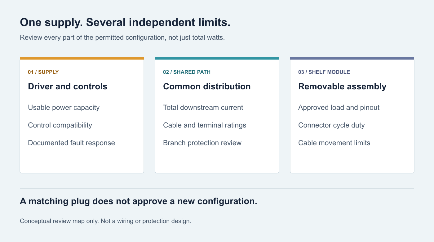
A daisy-chain harness does not remove this issue. Its first through-connection may carry the downstream total even if the last one carries only a single shelf. Conversely, a branch arrangement can simplify load allocation but still needs a correctly rated common feed. Do not treat either layout as automatically superior.
For multi-channel systems, review the actual current path through shared conductors and common terminals. A per-channel rating is not necessarily the permissible total for the assembly. Assess the maximum allowed scene, not only a dimmed showroom setting. RH’s power-supply sizing guide covers the source load budget; this shared-path check is additional.
3. Specify Three Different Connector Capabilities
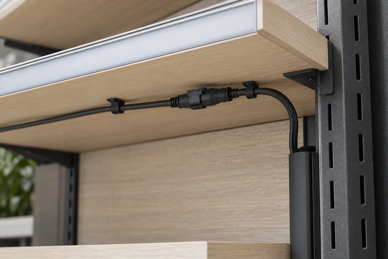
First, current capability: request the rating for the actual contact, conductor, number of loaded circuits, and temperature. Molex’s iGrid tin-plated connector specification, for example, provides current-derating data that varies with wire size and circuit count.[1] A headline amperage without its conditions is incomplete purchasing information.
Second, mating durability: define expected connect-disconnect cycles. One reconfiguration per month over five years represents about 60 cycles at an interface disconnected each time, before production checks or service interventions. That is a planning assumption, not a universal retail duty cycle. The cited Molex specification lists 30 durability cycles for its particular tin-plated system; that number is not transferable to other connectors or a prediction of the exact cycle at which a part will fail.
Third, connection under power: carrying current is different from making or breaking a circuit. Phoenix Contact explicitly states that the cited COMBICON connector has no switching capability and must not be connected or disconnected while energized or under load.[2] This illustrates a specification distinction, not a recommendation to use that particular connector on a shelf.
Unless the complete system is explicitly designed and documented for the intended powered operation, make reconfiguration an isolated-power task under the approved procedure. A dimming command or an app’s “off” state is not a substitute for electrical isolation.
Also specify polarization, compatible mating halves, latching, protection of unused outlets, and identification. Mechanical fit does not establish a matching pin assignment. Do not rely on housing color alone to prevent mixing incompatible module families. The connector-versus-soldering guide explains ordinary joint considerations; repeated shelf reconfiguration adds a separate duty requirement.
4. Distinguish Repositioning From Continuous Cable Movement
A lead that bends easily by hand is not necessarily designed for repeated movement. Record whether the cable is routed once, repositioned during occasional resets, or flexed whenever a drawer or pull-out shelf operates. Those uses can require different cable constructions and mechanical arrangements.
LAPP’s guidance on dynamic cable systems treats bending radius, cable construction, and motion conditions as linked selection factors.[3] The lesson for display design is to select the cable for its duty and available space. It is not to assign an industrial cable-chain life claim to an ordinary LED lead.
Review the highest and lowest permitted shelf positions. The lead should not pull on the connector at one extreme or form a snagging loop at the other. Clips and restraints should control the cable without crushing it. Keep it clear of shelf brackets, sharp edges, drawers, stock-handling areas, and pinch points.
Provide access to release the latch without pulling the wire. Leave sufficient service allowance where the component instructions permit it, but do not use an unrestrained excess coil as the routing solution. A removable shelf should not require staff to improvise cable management every time it moves.
5. Do Not Confuse Driver Protection With Branch Protection
A driver marked “short-circuit protected” does not, by that phrase alone, establish that every downstream lead and connector is protected appropriately. The designer must assess the supply’s fault behavior against the wiring and distribution arrangement, including any required branch protection.
MEAN WELL describes different protection behaviors, including shutdown, hiccup operation, and constant-current limiting.[4] Check the exact model’s data and recovery behavior. Do not assume all supplies with the same wattage respond identically or that a tripped supply makes a damaged harness suitable for continued use.
Decide the acceptable operational impact of a failed shelf. Should one defective module darken a whole wall, one bay, or only that module? That decision influences distribution and service design. It does not justify bypassing protective devices to keep unaffected lights on.
Fault-condition evaluation belongs to qualified personnel using an appropriate test plan. Store staff should not create shorts or repeatedly reconnect a suspect module to diagnose it. Define a removal-from-service and replacement process for damaged parts.
6. Keep Physical Bays and Control Groups Aligned
A shelf moved to a new bay can remain assigned to the old control group if addressing resides in its module. In another architecture, the shelf follows whichever controlled supply it is plugged into. Both can be workable, but the operational result must be deliberate.
Document whether the controlled unit is the driver output, bay, shelf module, or addressable device. Mark the associated connections and define what must be recommissioned when a component moves. A drawing that shows only power distribution is insufficient when the store expects independent scenes.
For tunable-white or RGBW modules, record channel order, permitted scenes, and behavior after supply interruption. Matching connector pole count does not demonstrate matching channel assignment. Test the complete driver-controller-module combination at the intended dimming range; do not infer compatibility from separate data sheets.
RH’s dimming-method guide supports that selection. The handover should also explain which changes staff may make without altering the approved electrical configuration.
7. Recheck the Light After the Shelf Moves
Electrical compatibility does not guarantee a good retail result. Raising a shelf can expose the source to customers; lowering it can bring the light closer to reflective packaging. A longer module may illuminate the product evenly but create a visible bright end beyond the merchandise.
Mock up the permitted position range with representative products and some empty shelf space. Review label visibility, shadowing, direct glare, and reflections from normal customer and staff viewpoints. Accept a range of usable configurations, not only the most flattering opening-day photograph.
Keep the optical assembly under control: strip, profile, diffuser, mounting angle, and end detail. A replacement cover with different transmission or a substitute strip with different output can upset the balance across a bay. The aluminum-profile guide explains why the housing is part of performance, while the color-consistency guide helps frame visual matching.
8. Standardize the Replacement Module, Not Only the Strip
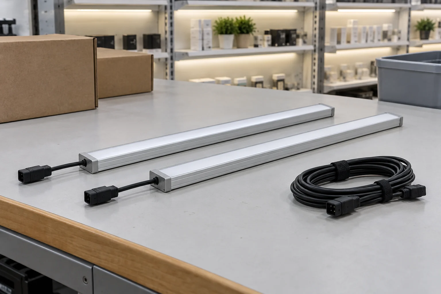
Define a service part as the agreed assembly, which may include the LED strip, profile, diffuser, end caps, lead, and connector. A roll of the original tape is not necessarily a useful spare if replacement requires opening joinery, remaking connections, or selecting an unknown diffuser.
Keep a controlled part identifier and compatibility list. Identify which revisions may be mixed, whether older modules need an adapter approved by the system designer, and how replacement color differences will be managed. An adapter that merely fits can defeat keying or introduce another underrated connection.
For multi-store rollouts, retain an approved reference assembly and the relevant drawings, supplier data, and control settings. Track component substitutions before they reach the field. RH’s LED replacement compatibility guide explains why equal voltage and similar appearance are not a complete equivalence check.
Specify access and replacement time as requirements to demonstrate in the mockup, not as invented promises. Have the intended service team show how it reaches the connection, releases the module, and restores the agreed configuration under the approved procedure.
9. Approve a Configuration Envelope Before Rollout
Use a structured release review covering normal operation, authorized reconfiguration, and foreseeable service needs. The supplier should identify which tests and limits apply to the selected assembly; a successful single-shelf power-on is not evidence for the fully populated bay.
| Review | Evidence to retain | Stop release when |
|---|---|---|
| Maximum permitted population | Load schedule for every common path and branch, applicable ratings, and protection assessment. | Only driver wattage has been checked. |
| Mechanical adjustment | Routing and retention verified across permitted shelf positions and motion duty. | Movement pulls the lead, defeats a latch, or traps the cable. |
| Connector duty | Exact parts, mating compatibility, durability, rating conditions, and powered-operation restrictions. | The answer is only “the plug fits.” |
| Control behavior | Group mapping, dimming compatibility, and power-restoration behavior. | A shelf changes groups unintentionally after relocation. |
| Optical consistency | Accepted configuration samples and approved replacement assemblies. | The approved effect depends on a single shelf height. |
| Service and compliance | Authorized procedures, accessible parts, and destination-market evaluation scope. | Component paperwork is presented as approval of the entire fixture. |
Confirm the applicable evaluation route with the responsible specialist for the target market. As one example, UL Solutions identifies UL 970 for retail fixtures and merchandise displays, including commercial showcases and temporary displays.[5] This is not a claim that every shelving project everywhere must use one standard, or that RH components confer certification on the finished display.
Selecting the Lighting Component
COB or high-density SMD can be considered according to the profile depth, source visibility, output, and optical requirements. Neither construction makes a system inherently modular. The harness, interface, distribution limits, and approved replacement process must be specified separately.
Plan for the next merchandising reset
Send RH Strip Lighting your fixture drawings, permitted shelf configurations, module lengths, operating scenes, and service expectations. Request available model-specific information and samples. Confirm any custom harness or modular-assembly capability before including it in the purchasing specification.
Discuss a Modular Shelf Lighting ProjectA modular lighting system should reduce decisions in the store, not transfer unresolved engineering to store staff. Define the permitted combinations, prevent incompatible connections, and make approved replacements easy to identify. That is what allows the display to remain useful after its first layout changes.
References
- Molex: iGrid 2.0 Wire-to-Board Connector System, Tin-Plating Product Specification. Sections 4.3–4.5 distinguish current derating, temperature, and durability. Specific component example, not an RH rating or retail connector recommendation.
- Phoenix Contact: PC 4/4-ST-7,62 BD:DC+DC-, part 1718708. Operating notes distinguish current-carrying capability from connection or disconnection while energized.
- LAPP: Understanding Dynamic Load-Bearing Capacity in Cable Chains. Background on motion, bend radius, and cable construction; industrial flex-life claims are not applied to shelf leads.
- MEAN WELL: Notes on LED Drivers & Luminaires. Note 1.5 describes differing overload-protection behaviors; the selected model’s current specification governs.
- UL Solutions: Retail Fixtures and Commercial Displays. Overview of finished-display evaluation and UL 970; not a certification claim for the proposed installation.
Request a Project or Trade Quote
Sourcing for an installation project, resale or OEM production? Share your requirements below. You can discuss project samples before committing to a bulk order.
Related Articles

LED Strip Lighting After a Power Outage: Designing a Reliable Restart
Plan LED strip power restoration beyond total watts. Review driver inrush, switching limits, restart scenes, and commissioning before project handover.

Why LED Strip Lights Buzz When Dimmed: A Guide for Quiet Spaces
Diagnose LED strip buzzing without guessing. Review drivers, PWM controls, mounting resonance, and low-level acoustic acceptance for quiet interiors.

LED Strip Lighting for Wine Cellars and Bottle Displays: Beyond Warm White
Design wine-display LED lighting around spectrum, exposure time, label visibility, and heat. Learn why warm white and low UV are…